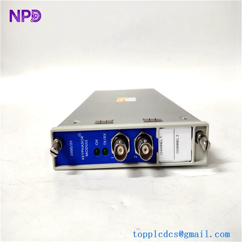

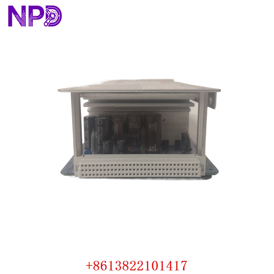
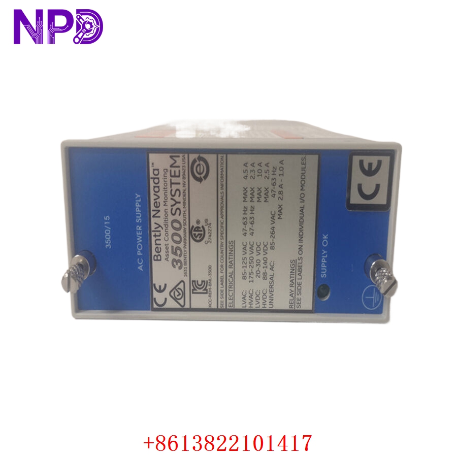
Description
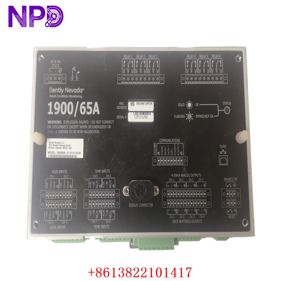
- Model: Bently Nevada 167699-02 (1900/65A)
- Brand: Bently Nevada (Baker Hughes)
- Series: 1900/65A Equipment Monitor Series
- Core Function: Provides continuous monitoring and protection for rotating equipment (e.g., pumps, fans, compressors)
- Product Type: Equipment Monitor / Vibration Protection Module
- Key Specs: 4 channels, programmable alarm setpoints, digital communication (Modbus/Ethernet)
- Input Channels: 4 independent sensor inputs
- Sensor Compatibility: Accelerometers, velocity sensors, or proximity probes
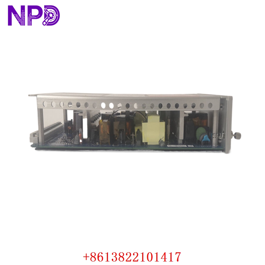
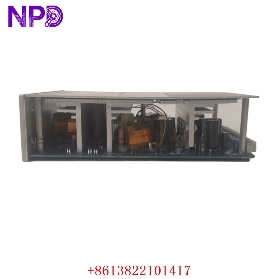
- Power Supply: 24 V DC (18–36 V DC range)
- Communications: Modbus TCP/IP (Ethernet) and RS-485
- Relay Outputs: 4 programmable alarm/trip relays
- Sampling Rate: Up to 40 kHz per channel
- Mounting: DIN Rail or panel mount
- Configuration: Via 1900 Configuration Software (USB/Ethernet)
- Ingress Protection: IP20
Application Scenarios & Engineering Pain Points
The 1900/65A is the backbone of balance-of-plant (BOP) machinery protection. In refineries or power plants, a single pump failure can cause a cascade of process issues. Engineers often struggle with “data islands”—where monitor data is siloed in the local cabinet. The 167699-02 solves this by bridging the gap between raw sensor signals and the site’s SCADA/DCS network via Modbus.
Typical Application Scenarios:
- Power Generation – Auxiliary Equipment Monitors vibration levels on cooling tower fans and circulating water pumps to prevent mechanical fatigue.
- Oil & Gas – Centrifugal Compressors Provides critical seismic monitoring and case vibration protection for secondary process compressors.
- Water Treatment – High-Pressure Pumps Tracks bearing wear and shaft misalignment, allowing for predictive maintenance scheduling.
Case Study: Retrofitting Aging BOP Assets A large chemical plant had several legacy vibration monitors that were failing. The plant was experiencing “nuisance trips” because the old analog relays were drifting, causing unnecessary production halts. We supplied the 1900/65A to replace the obsolete units. By integrating the Modbus data into their centralized DCS, they gained real-time insight into vibration trends rather than just waiting for a high-alarm trip. The facility reported a 15% reduction in unplanned downtime within the first six months.
Troubleshooting Quick Reference
Don’t let a “Not Ready” status keep your machine down. Use this logic to isolate the fault.
| Failure Symptom | Possible Cause | Quick Check Method | Recommended Action |
|---|---|---|---|
| “Module Not Ready” LED | Internal Self-Test Fail | Check Status LED via Config Software | Review error logs; likely hardware fault |
| No Sensor Signal | Faulty Wiring/Sensor | Measure mV output at terminal | Verify sensor power (–24 V DC) |
| Alarm Trip (False) | Setpoint Drift | Compare actual value vs. setpoint | Re-verify config file parameters |
| Comm Loss (Modbus) | Network Configuration | Ping IP; check RS-485 termination | Verify Slave ID and baud rate |
Engineer’s Note: ❗ Wiring Tip: The 1900/65A is sensitive to ground loops. When wiring, ensure the cable shield is terminated to a single, clean instrumentation ground at the monitor end only. Using a multimeter to check for voltage between the sensor shield and the enclosure ground (should be < 0.5 V) often saves hours of chasing “phantom” noise.