Description
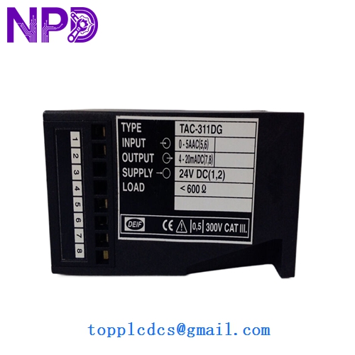
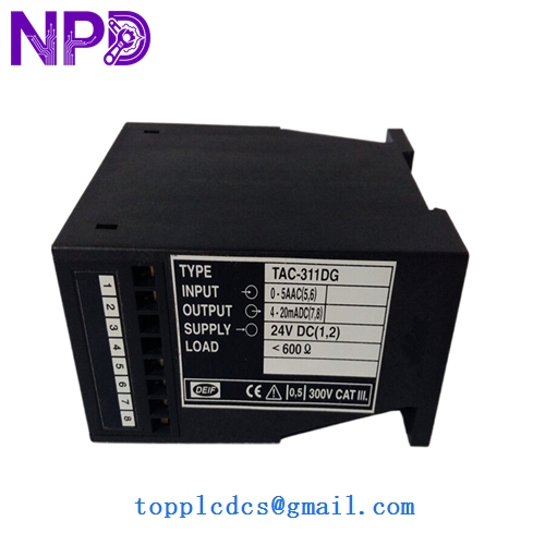
- Model: DEIF TAC-311DG (Part No. 2961300020)
- Brand: DEIF (Denmark)
- Series: TAC (Digital Multi-transducer Series)
- Core Function: High-precision measurement and conversion of AC electrical parameters into digital/analog signals.
- Product Type: Digital Multi-Transducer
- Key Specs: 3-Phase AC RS485 Modbus RTU DIN Rail Mount
Key Technical Specifications
- Input Voltage: 100 V to 690 V AC (Phase-to-Phase)
- Input Current: 1 A or 5 A AC (Configurable via CT ratio)
- Frequency: 45 Hz to 65 Hz
- Accuracy Class: 0.5 (Measurement of Voltage, Current, Power)
- Communication: RS485 (Modbus RTU protocol)
- Analog Output: 3x Programmable outputs (e.g., 4-20 mA or 0-10 V)
- Auxiliary Supply: 24 V to 250 V DC / 110 V to 230 V AC
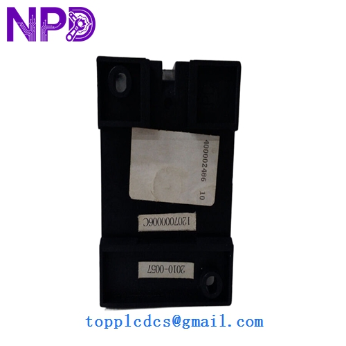
- Mounting: 35 mm DIN rail (Standard)
- Enclosure Rating: IP20
- Configuration Interface: Via DEIF PC tool or front-panel configuration
DEIF TAC-311DG
DEIF TAC-311DG
DEIF TAC-311DG

DEIF TAC-311DG
Installation & Configuration Guide
Phase 1: Preparation (Pre-Installation)
Estimated time: 10 minutes
⚠️ Safety First:
- Ensure the main power bus is de-energized. You are dealing with high-voltage AC inputs.
- Verify that your Current Transformers (CTs) are correctly sized (1 A or 5 A secondary).
- Check the auxiliary power range. The TAC-311DG has a wide power supply range, but it’s always better to measure the supply voltage before connecting.
Required Items:
- 35 mm DIN Rail.
- Shielded twisted pair cable for RS485 communication.
- DEIF Utility Software (optional, for advanced programming).
Phase 2: Wiring and Connection
Estimated time: 15 minutes
Step 1: Voltage Inputs Connect the voltage sensing lines to terminals L1, L2, L3, and N. For systems up to 690 V, direct connection is standard. For higher voltages, use Potential Transformers (PTs).
Step 2: Current Inputs Connect the CT secondaries to the corresponding current terminals. Note: Never open-circuit a CT while the primary is energized—this can create lethal voltages and destroy the transducer.
Step 3: Communication & Output Connect the RS485 A/B terminals. If this is the last device on the Modbus loop, ensure a 120 Ω termination resistor is installed.
Phase 3: Configuration & Testing
Estimated time: 10 minutes
- Power Up: The display or status LED should illuminate.
- Set CT/PT Ratios: Use the front buttons or PC software to input your transformer ratios (e.g., 1000/5A). Without this, your readings will be scaled incorrectly.
- Modbus Addressing: Assign a unique Slave ID and match the Baud Rate (usually 9600 or 19200) to your PLC or SCADA system.
- Verification: Compare the readings on the TAC-311DG display with a handheld clamp meter to ensure the phasing is correct.
Customer Cases & Industry Applications
Case 1: Marine Generator Monitoring System Upgrade A cargo vessel was experiencing erratic power readings on its main switchboard. The old analog transducers were drifting due to engine room heat and vibration. We supplied five TAC-311DG units as a digital upgrade. By using the RS485 Modbus interface, the crew integrated the generator data directly into the ship’s Alarm and Monitoring System (AMS). The high accuracy (Class 0.5) allowed for better load-sharing between engines, reducing fuel consumption by 2%.
Case 2: Industrial Data Center Energy Management A large data center in Frankfurt required precise billing-grade measurement for its cooling plant. They needed a transducer that could handle a wide voltage range and provide multiple analog outputs for local control while feeding digital data to the Building Management System (BMS). The TAC-311DG was chosen for its reliability and “all-in-one” measurement capability. By consolidating several individual meters into one DEIF unit, the client saved 30% on cabinet space and 20% on wiring costs.
Frequently Asked Questions (FAQ)
Q: Can I use this unit on a single-phase system? A: Yes. While the TAC-311DG is designed for 3-phase systems, it can be configured for single-phase or 2-phase operation via the configuration menu. Just ensure the unused inputs are handled according to the manual.
Q: How do I know if I have the “DG” version or the standard “TAC-3” version? A: The “DG” designation typically refers to specific configuration or marine-approved variants (often for generator applications). Check the part number 2961300020 on the side label. We only sell the official DG version as specified.
Q: Does it come with a calibration certificate? A: Every DEIF unit we sell is a “New Surplus” or “Original New” item that has passed factory calibration. While a physical paper certificate isn’t always in every box, the unit’s serial number carries the calibration data in DEIF’s database.
Q: Can I configure the 4-20 mA outputs to represent any parameter? A: Absolutely. You can map the analog outputs to represent Phase Voltage, Line Current, Active Power (kW), Reactive Power (kVAR), or Frequency. This is done through the free DEIF utility software or the front-panel interface.
Q: What is the lead time for 5 units? A: We currently have these in stock in our Shenzhen warehouse. For 5 units, we can usually test, pack, and ship within 24-48 hours. Express delivery to most international locations takes about 5-7 business days.