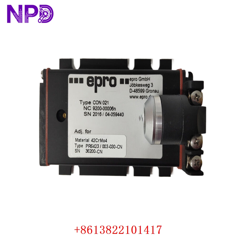
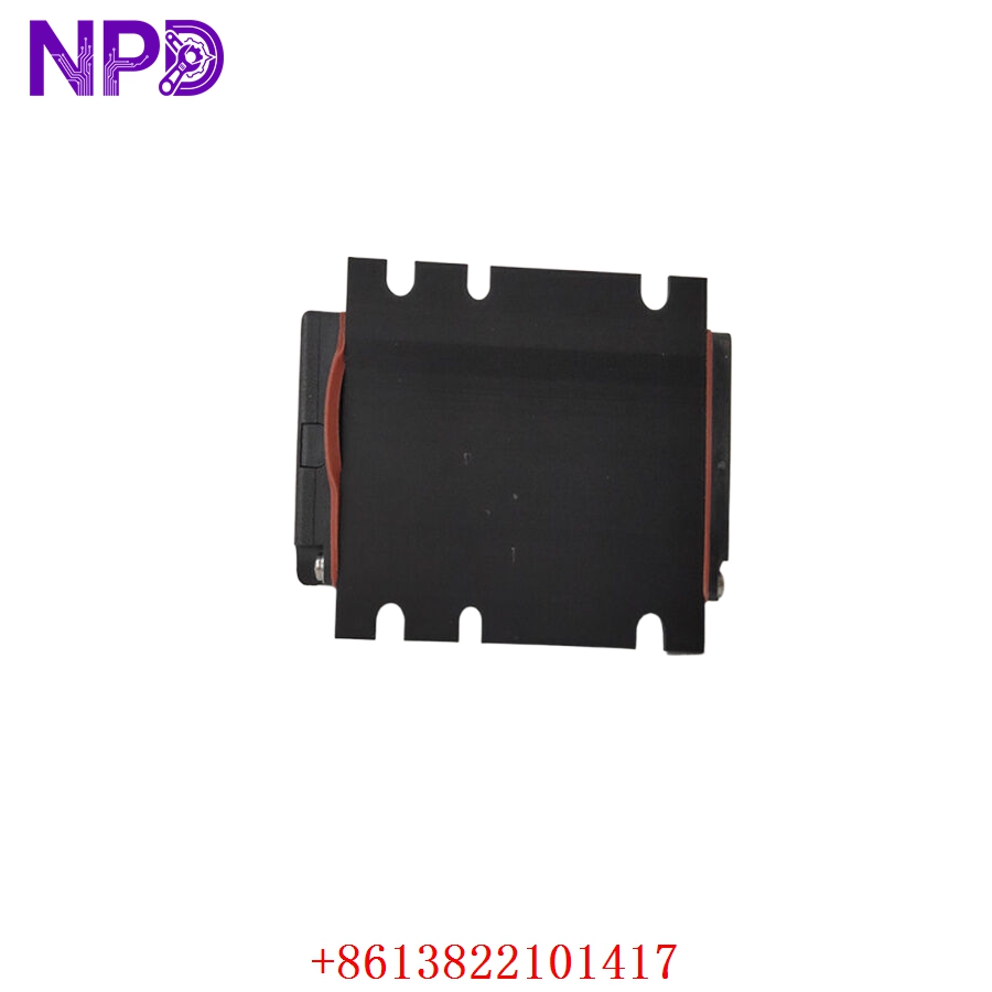
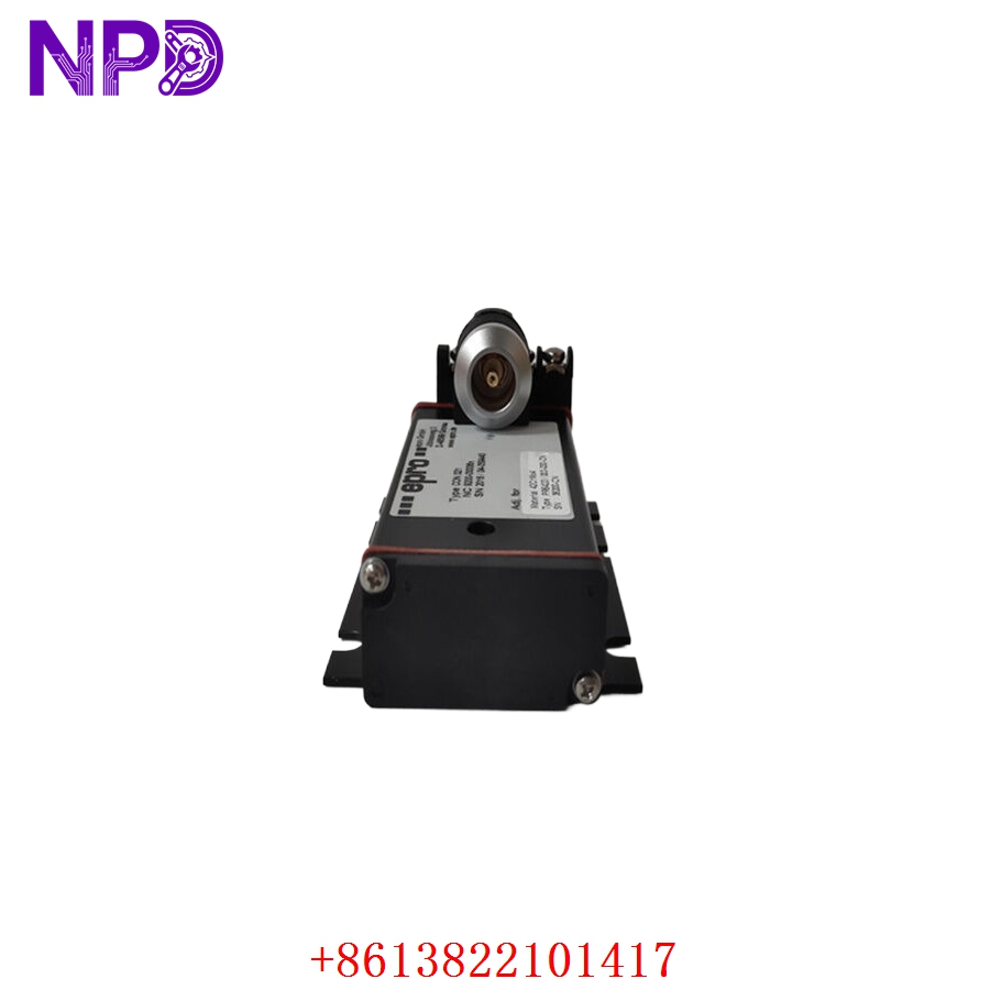
Description
- Model: EPRO CON021 (9200-00006N)
- Brand: EPRO (Emerson)
- Series: MMS 6000 Series (or related vibration monitoring systems)
- Core Function: Converts high-frequency signals from proximity sensors into usable industrial signals (4–20 mA or raw voltage) for vibration and position monitoring.
- Product Type: Signal Converter / Condition Monitoring Module
- Key Specs: Compatible with proximity probes (eddy current sensors), linearized output
- Input: Signals from standard eddy current proximity probes
- Output: Proportional DC voltage or 4–20 mA (depending on configuration)
- Frequency Response: Optimized for machinery vibration (often 0 Hz to 10 kHz range)
- Power Supply: 24 V DC (standard instrumentation power)
- Galvanic Isolation: Integrated to prevent ground loop noise
- Mounting: DIN rail or system rack mount
- Calibration: Trimmable via front-panel potentiometers for gap/sensitivity offset
- Protection: RFI/EMI shielded for industrial environments
Application Scenarios & Engineering Pain Points
The CON021 is a critical link in turbine protection systems. The primary engineering challenge is “linearization error.” Eddy current probes are highly sensitive to the physical properties of the target material (the shaft). If the converter is not correctly matched to the probe type and target material conductivity, the vibration data will be non-linear, leading to false “High-Vibration” trips during turbine startup.
Typical Application Scenarios:
- Power Generation – Steam/Gas Turbines Monitors shaft radial vibration and axial displacement (thrust position).
- Oil & Gas – Centrifugal Compressors Detects shaft orbit deviations and misalignment in high-speed rotating equipment.
- Heavy Industry – Large Fans/Motors Provides long-term condition monitoring for bearing health.
Case Study: Eliminating Startup Nuisance Trips A power plant reported that their turbine system tripped consistently during warm-up sequences. Analysis showed that as the turbine shaft warmed up, the gap between the probe and the shaft changed, and the CON021 was incorrectly scaling this thermal expansion as a high-vibration event. By re-calibrating the gap voltage offset on the converter and updating the protection logic in their DCS, we allowed the system to account for thermal expansion. This saved the plant from three unnecessary emergency shutdowns per year.
Troubleshooting Quick Reference
Don’t assume a sensor is faulty before checking the converter’s output. A noisy signal is often just a ground loop issue.
| Failure Symptom | Possible Cause | Quick Check Method | Recommended Action |
|---|---|---|---|
| No Output Signal | Loss of Power | Measure 24 V DC at input terminals | Check instrumentation power fuse |
| Signal “Rail” (Max/Min) | Probe Cable Damage | Disconnect probe; check impedance | Replace proximity probe/cable |
| Noisy/Jittery Data | Ground Loop | Check signal shield continuity | Ensure single-point grounding |
| Calibration Drift | Sensitivity Mismatch | Verify target material vs. scale | Re-trim span/offset potentiometers |
Engineer’s Note: ❗ Crucial Advice: Always perform a “Bench Check” before installation. Use a static target (a piece of steel of the same material as the shaft) and a feeler gauge to verify the CON021 output voltage at specific gaps (e.g., 0.5 mm, 1.0 mm, 1.5 mm). If the output does not match the factory calibration table, the converter needs re-trimming or is internally degraded.