Description
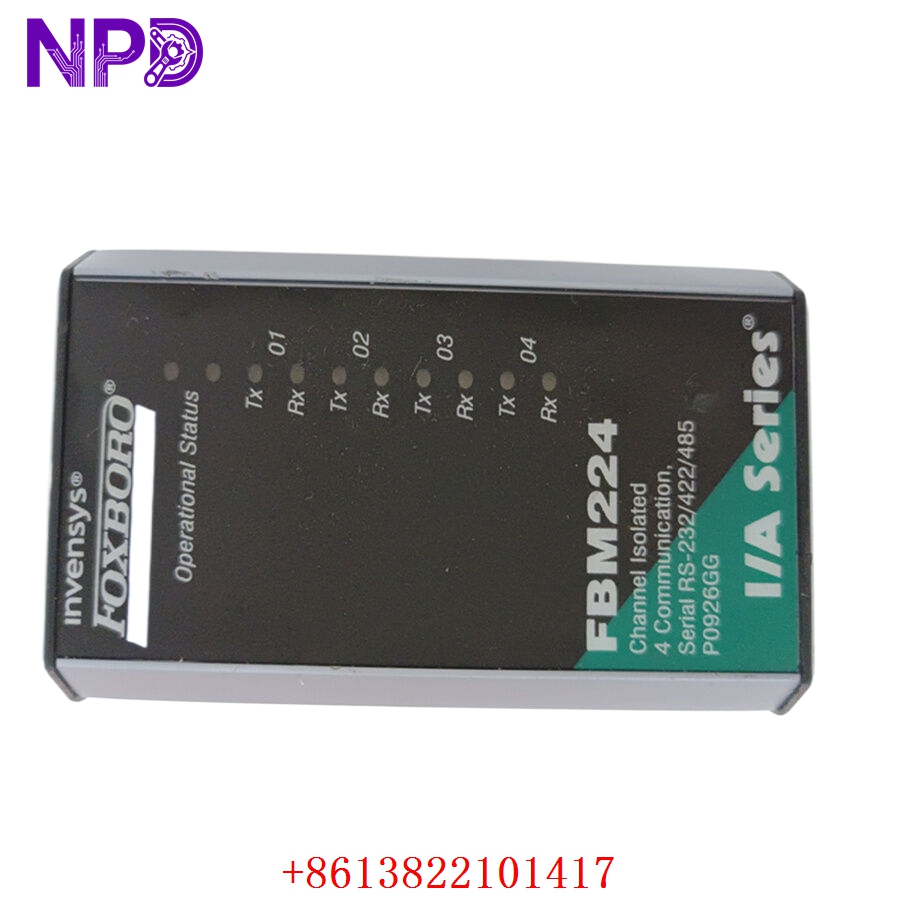
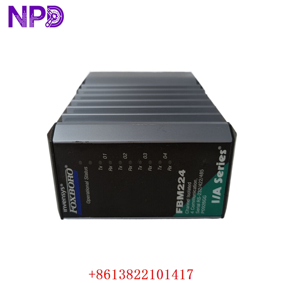
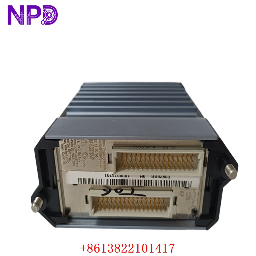
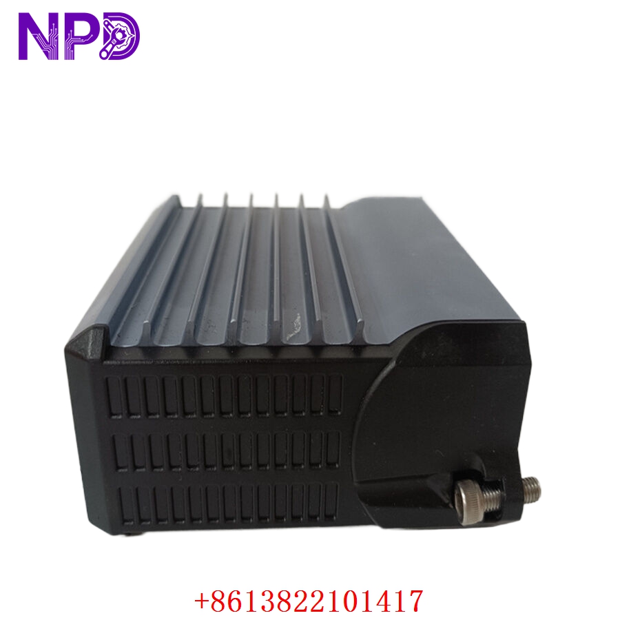
- 🔢 Model: FBM224 (Part Number: P0926GG)
- 🏢 Brand: Foxboro (Invensys/Schneider Electric)
- ⛓️ Series: I/A Series Fieldbus Module (FBM)
- 💡 Core Function: High-density digital I/O interface for process control
- 🛠️ Type: Digital Input/Output Module
- ⚡ Key Specs: Supports 16 channels, configurable input/output states
- 🔢 Channel Count: 16 configurable digital I/O channels
- ⚡ Voltage Range: 24 V DC (standard industrial logic level)
- 🛡️ Isolation: Galvanic isolation between channels and bus
- 🌡️ Operating Temp: 0°C to 60°C
- 🔩 Mounting Type: DIN rail mounted baseplate
- 🛡️ Protection Rating: IP20
- 💡 Status Indicators: Per-channel I/O state and module health LEDs
- 🛠️ Configuration: Configured via Foxboro I/A Series control software
Installation & Configuration Guide
Phase 1: Preparation (15 mins)
⚠️ Safety First:
- Before handling, verify the baseplate is de-energized to prevent short circuits on the I/O bus.
- 🧤 Use an anti-static wrist strap; the FBM224 circuitry is highly sensitive to ESD.
- Confirm the field wiring matches the terminal assignment documentation.
Phase 2: Removal & Installation (20 mins)
- 📸 Record Settings: Before disconnecting, verify the slot position and channel wiring labels.
- 🔩 Detachment: Use a screwdriver to release the locking tabs on the top and bottom of the module. Pull the module straight out from the baseplate.
- 📥 Insertion: Align the module with the baseplate connectors. Press firmly until it locks securely into place.
- 🔌 Wiring: Ensure terminal blocks are seated firmly. Poor contact can lead to “noisy” signals and erratic bit-flipping in your process logic.
Phase 3: Testing & Commissioning (15 mins)
- 🟢 Power-Up: Observe the LEDs. A solid green “Module Status” light indicates successful initialization.
- 📡 Bus Handshake: Check the Foxboro I/A Series workstation to ensure the module is “Online” and communicating.
- 🔄 I/O Verification: Manually toggle field devices (or use a signal generator) to confirm that the workstation receives the correct state changes.
- 🩺 Diagnostics: Review the module’s error logs in the I/A Series software for any checksum or parity errors.
Customer Cases & Industry Applications
Case: Emergency Digital I/O Restoration
- Situation: A petrochemical facility relied on the FBM224 (P0926GG) to monitor critical safety-trip switches.
- Task: One module failed due to internal power supply degradation, triggering an “I/O Failure” alarm that forced the line into a safe-state shutdown.
- Action: They found the part in our surplus inventory. We performed a full functional test of the 16 channels to ensure zero bit-errors before shipping.
- Result: Installation was completed during a night shift. The system recognized the module immediately without requiring software re-compilation, preventing a scheduled 48-hour downtime for system maintenance. The customer has since added two units to their “critical spare” shelf.
Frequently Asked Questions (FAQ)
Q: Is the P0926GG exactly the same as the FBM224? A: Yes, FBM224 is the series/model designation, while P0926GG is the specific Foxboro part number. They are interchangeable.
Q: Why does my FBM224 show a “Module Error” light? A: This usually indicates a communication fault on the FBM bus or an internal hardware failure. First, try re-seating the module. If the error persists, check the Foxboro workstation diagnostic screen for specific error codes—this will tell you if the fault is bus-side or field-side.
Q: Is this unit new? A: We provide New Surplus modules. These are genuine, unused Foxboro components. We do not sell “refurbished” units, as the reliability of digital I/O in control loops is too critical to risk with aging, repaired electronics.
Q: Can I replace this while the system is running? A: Foxboro I/A Series hardware generally supports “Hot Swapping.” However, always consult your specific I/O baseplate and chassis documentation to ensure it is configured for live insertion before pulling the module. If in doubt, power down to avoid potential damage to the baseplate connectors.