
Description
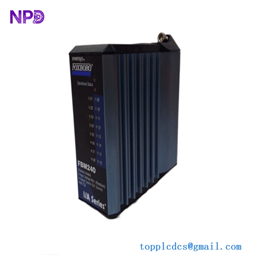
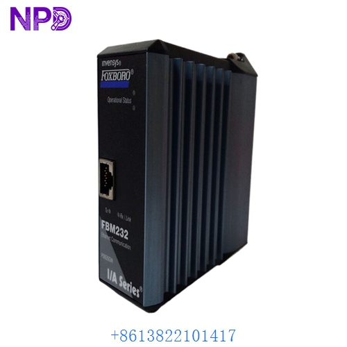
The Foxboro FBM232 (P0926GW) is a high-performance Fieldbus Module designed for use within the Foxboro I/A Series Distributed Control System (DCS). This module serves as a critical interface for the FOUNDATION Fieldbus H1 communication protocol. It enables the control system to communicate directly with smart field devices, such as pressure, temperature, and flow transmitters, providing both process data and advanced diagnostic information for enhanced process management.
Technical Specifications
| Parameter | Detail |
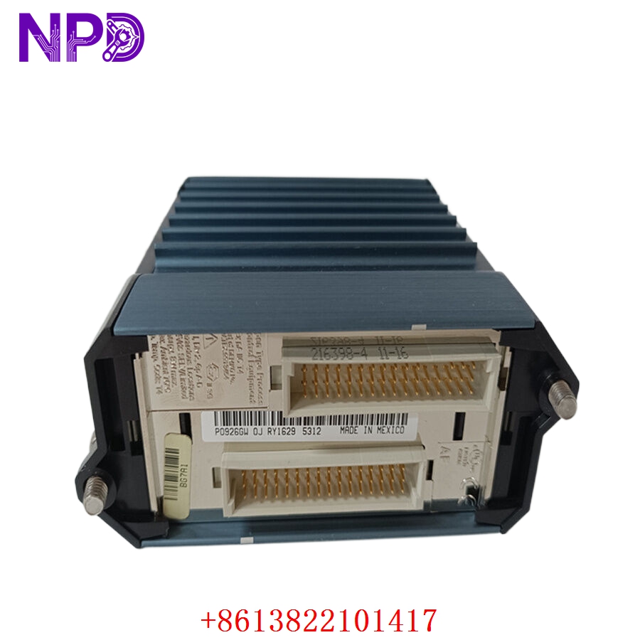
| Model | FBM232 |
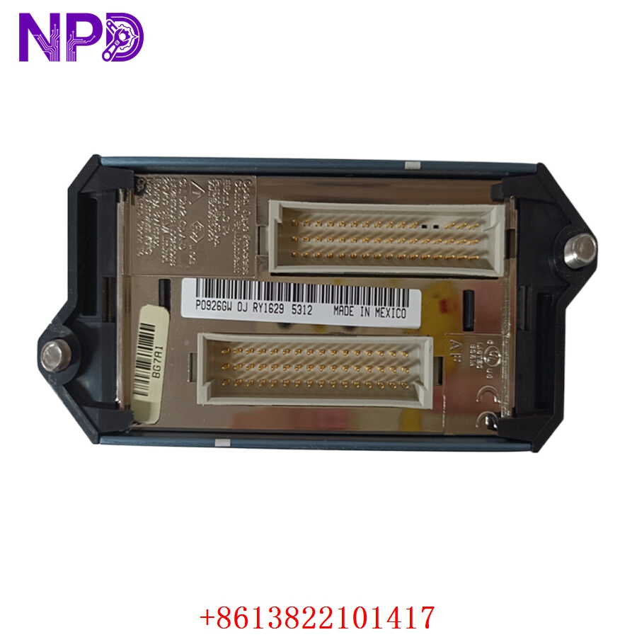
| Part Number | P0926GW |
| Manufacturer | Foxboro (Schneider Electric) |
| Device Type | FOUNDATION Fieldbus H1 Module |
| Protocol | FOUNDATION Fieldbus H1 (IEC 61158) |
| Number of Channels | 4 (H1 Segments) |
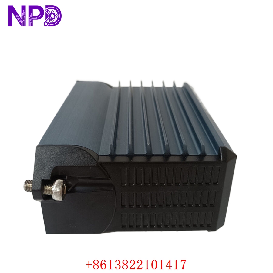
| Mounting | I/A Series Fieldbus Module Baseplate |
| Operating Temperature | -20°C to +60°C |
Fields of Application
The FBM232 is deployed in complex industrial environments requiring high-density integration of smart field instruments, including:
- Oil and Gas: Precise monitoring of remote valve positions and flow rates in refineries.
- Chemical Processing: Integration of multi-variable smart sensors for reaction control.
- Power Generation: High-speed data acquisition for boiler and turbine auxiliary monitoring.
- Water/Wastewater: Monitoring of large-scale pumping stations and treatment chemical levels.
Product Introduction
The P0926GW FBM232 functions as a gateway between the I/A Series control network and the FOUNDATION Fieldbus H1 segments. Unlike traditional analog I/O that requires one pair of wires per sensor, this module supports multiple devices on a single segment, significantly reducing wiring costs. It performs essential signal processing, timing, and communication management, ensuring that data from field instruments is accurately timestamped and synchronized with the control system’s execution cycle.
Product Use Instructions
To integrate the FBM232 into your system:
- Ensure the fieldbus baseplate is correctly mounted and powered.
- Insert the FBM232 module into the designated baseplate slot until the connector is firmly seated.
- Secure the module using the provided locking mechanism.
- Connect the H1 fieldbus segments to the appropriate terminals on the baseplate, ensuring proper termination resistors are installed at the end of each segment.
- Use the I/A Series configuration software to map the FOUNDATION Fieldbus devices to the control strategy.
- Verify the module status via the front-panel LEDs; a steady green light indicates successful communication with the control network.
Product Use Precautions
The FBM232 is sensitive to electrical noise; ensure that fieldbus cables are properly shielded and grounded in accordance with the FOUNDATION Fieldbus installation guidelines. Do not perform hot-swapping if the specific baseplate or cabinet safety rating prohibits it. Maintain a clean cabinet environment to prevent the accumulation of conductive dust, which can affect the high-frequency communication signals on the baseplate. Always use recommended cable types to prevent impedance mismatches.
Frequently Asked Questions (Q&A)
Q: Does the FBM232 provide power to the field devices?
A: The module itself does not provide power to the field devices. You must use an external Fieldbus Power Supply (FPS) to power the devices on the H1 segments.
Q: How many devices can be connected to the FBM232?
A: The number of devices depends on the power requirements of the instruments and the total segment length. Typically, you can connect up to 16-32 devices per segment, limited by the power supply and bus length constraints.
Q: What do the diagnostic LEDs indicate?
A: The LEDs typically indicate “Module Status” (health of the FBM) and “Comm Status” (communication activity on each H1 segment). A blinking red light often points to a configuration error or a communication fault on a specific segment.
Product Operation Methods
Once configured, the FBM232 operates as a transparent interface. It continuously scans the H1 segments for updated process values and diagnostic data from field devices. It then formats this information into data packets compatible with the I/A Series Control Processor. If a field device reports an error (e.g., sensor failure), the FBM232 captures this diagnostic information and pushes it to the control system, where it is visualized on the operator HMI as a device-level alarm.