Description
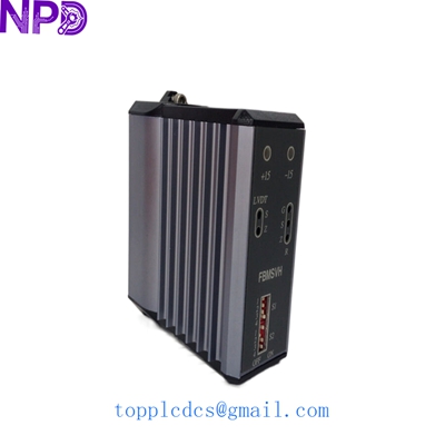
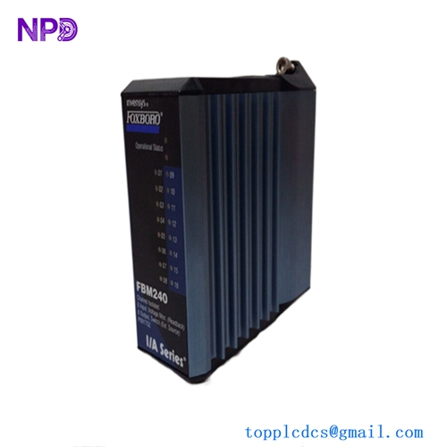
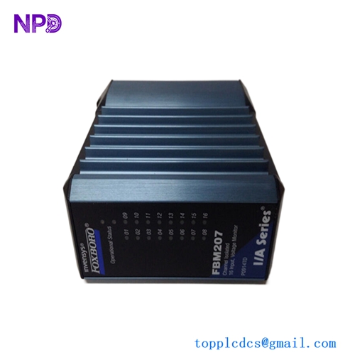
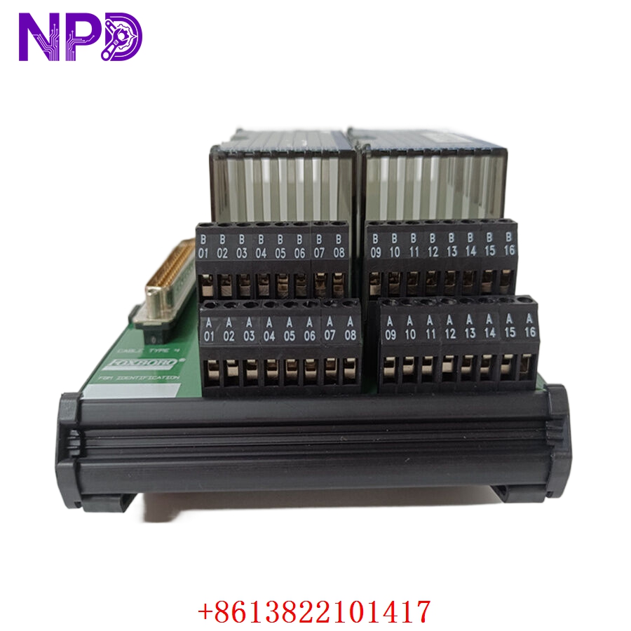
The Foxboro P0916PH and P0916JS are essential hardware components within the Foxboro I/A Series Distributed Control System (DCS). These components typically function as baseplates or terminal mounting assemblies designed to support the FBM (Fieldbus Module) architecture. They provide the physical and electrical foundation required to mount control modules and distribute power and communication signals between the field instrumentation and the I/A Series control processors.
Technical Specifications
| Parameter | Detail |
| Model | P0916PH / P0916JS |
| Manufacturer | Foxboro (Schneider Electric) |
| Device Type | I/O Baseplate / Mounting Assembly |
| System Compatibility | Foxboro I/A Series / Evo |
| Mounting | Cabinet Rack-mount / DIN Rail |
| Connectivity | FBM Backplane / Bus Interface |
| Environmental Rating | Standard Industrial Enclosure |
Fields of Application
These baseplates are utilized across major process industries where Foxboro I/A Series systems are installed, including:
- Refining and Petrochemicals: Housing I/O modules for critical valve and sensor control.
- Power Generation: Supporting the rack-mounted architecture of boiler and turbine controls.
- Large-Scale Manufacturing: Providing the scalable I/O density needed for complex automated sequences.
- Water/Wastewater: Serving as the termination point for distributed field sensors.
Product Introduction
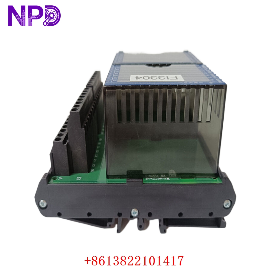
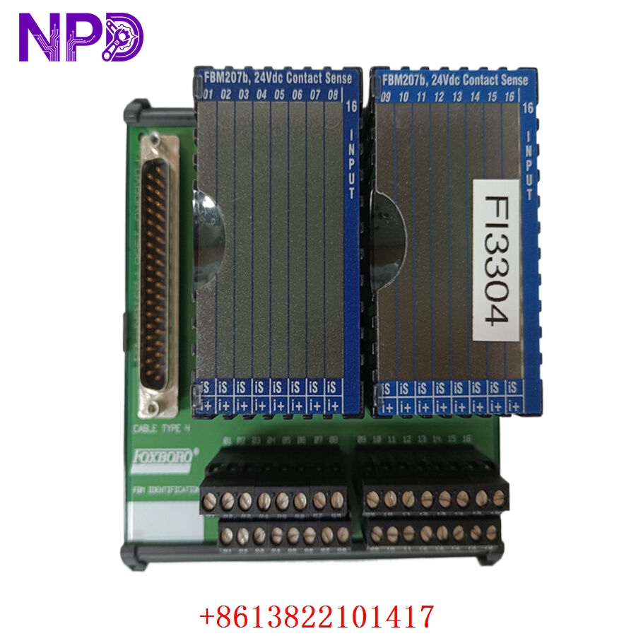
The P0916PH and P0916JS are designed to ensure high signal integrity in challenging environments. The baseplate architecture acts as a “motherboard” for the I/O modules, handling the bus communication and power distribution so that individual modules can be easily inserted or removed. The robust mechanical design ensures that connections remain stable even in high-vibration scenarios typical of heavy industrial facilities.
Product Use Instructions
- Mounting: Secure the baseplate to the cabinet’s internal mounting rail, ensuring the assembly is perfectly level and grounded to the cabinet’s main ground bus.
- Termination: Connect the primary power distribution cabling to the power input terminals of the baseplate.
- Module Installation: Insert your I/O modules (FBMs) into the specific slots provided on the baseplate, ensuring they lock into the backplane connectors.
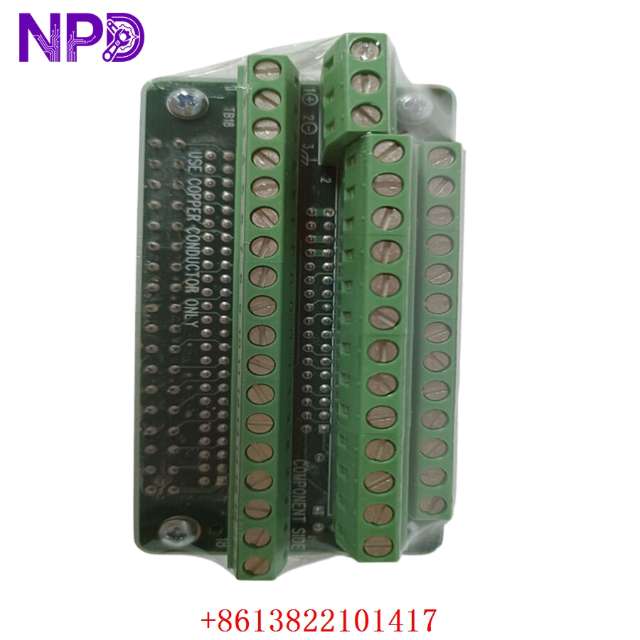
- Field Wiring: Terminate individual field sensor wires to the corresponding terminal blocks on the P0916 assembly, using cable ties for strain relief.
- Validation: Check the power rail voltage at the baseplate terminals before inserting expensive control modules to ensure no short circuits exist in the wiring.
Product Use Precautions
Ensure that the baseplate is properly bonded to the cabinet ground; a poor ground can lead to excessive electrical noise and signal “jitter” on analog loops. Do not over-torque the terminal screws, as this can damage the internal plastic housing of the assembly. Always keep the baseplate free of dust and metallic filings during installation, as these can bridge contacts and cause intermittent communication failures. Avoid using high-pressure air cleaning directly on the backplane connectors.
Frequently Asked Questions (Q&A)
Q: What is the functional difference between the PH and JS variants?
A: These designators typically refer to specific revision levels or mechanical variations (such as conformal coating for corrosive environments or specific terminal block spacing). Always match the replacement part number exactly with your existing cabinet documentation to ensure layout compatibility.
Q: Can I replace a baseplate while the system is running?
A: No. Unlike some FBM modules that support hot-swapping, the baseplate is a passive distribution unit. Replacing it requires a full system shutdown and the disconnection of all field wiring.
Q: How do I know if the baseplate is causing a communication error?
A: If multiple modules on the same baseplate are reporting “Communication Failure” simultaneously, it is a strong indicator of a backplane or power issue at the P0916 level.
Product Operation Methods
The P0916PH/JS operates passively. It contains printed traces that route power from the main bus to the FBMs and communication traces that connect the module’s data bus to the primary control network. During normal operation, the only “activity” is the distribution of voltage and the transmission of data. Periodic inspection is limited to ensuring the terminal connections remain tight and free of oxidation due to environmental exposure.