Description
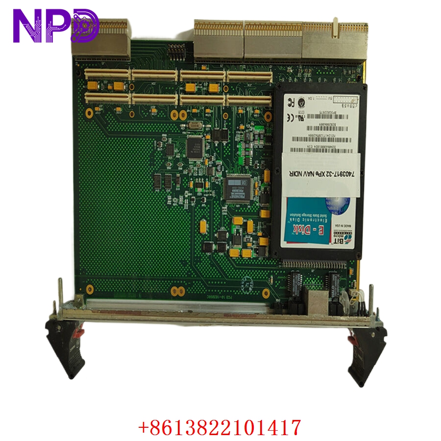
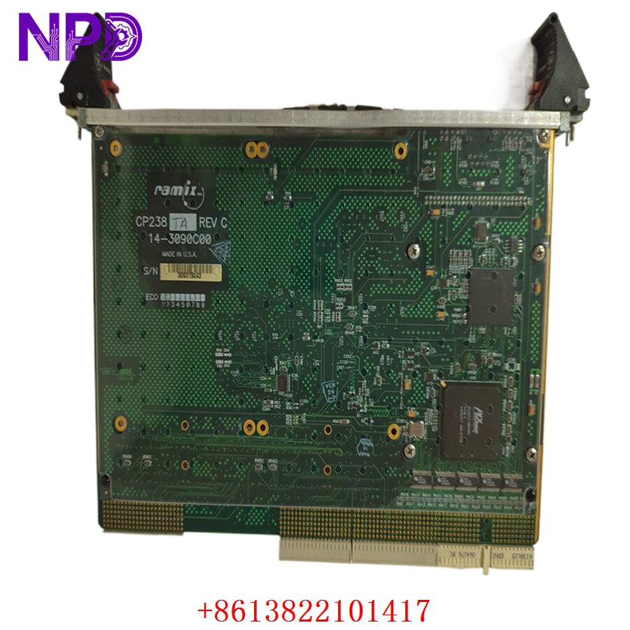
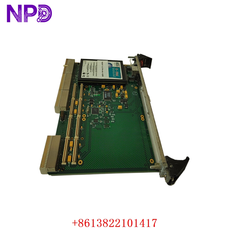
- Model: CP238TA
- Brand: GE (General Electric / GE Fanuc / GE Automation)
- Series: Industrial Automation Interface Family
- Core Function: Serves as a localized interface/control module for industrial automation racks, managing signal conditioning or I/O routing for automated machinery.
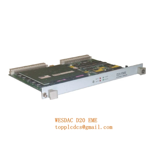
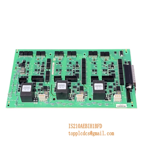
- Product Type: Interface Module / Logic Control Board
The GE CP238TA is a specialized module often utilized in legacy industrial control frameworks to facilitate communication between field devices and central processing units.
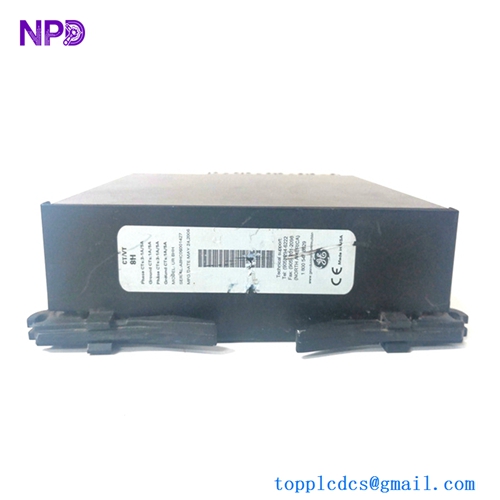
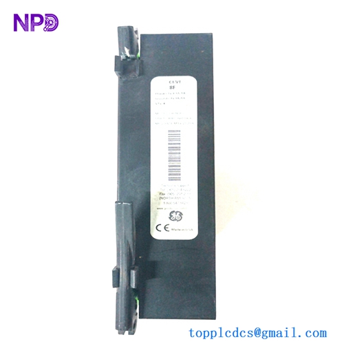
- Interface Architecture: Designed for integration into standard GE automation racks or distributed I/O chassis.
- Signal Handling: Provides necessary voltage level shifting and optical/galvanic isolation to protect sensitive processor logic from field-side voltage spikes.
- Diagnostic Features: Typically includes status LEDs to indicate power health and active communication link status.
- Robustness: Engineered for high-temperature and high-vibration industrial environments.
GE CP238TA
GE CP238TA
GE CP238TA
Engineering & Troubleshooting
The On-Site Reality
Modules like the CP238TA are often the “middle-man” in a control loop. When a machine controller stops receiving signals from a sensor—or fails to send a command to an actuator—the interface board is frequently the site of the fault. Because these modules often work in conjunction with high-current field devices, they are susceptible to inductive kickback and grounding loops.
Troubleshooting Quick Reference
❗ SAFETY FIRST: Always verify that the control rack power supply is isolated and the system is in a safe, non-operational state before removing or inserting any interface modules.
- LED Status Check:
- No Power LED: Check the 24 V DC backplane voltage. If the voltage is present at the rack bus, the module’s internal power protection circuitry has likely triggered (usually due to a transient surge).
- Flashing/Error LED: Indicates a communication handshake failure or an internal parity error within the module’s logic array.
- Signal Continuity: If the status lights are green but field signals are not passing through, use a digital multimeter to check for an open circuit at the terminal block interface. These modules often employ onboard protection diodes that can fail open if exposed to reverse-polarity field wiring.
- Contact/Termination Issues: Inspect the rear backplane connectors for signs of oxidation or bent pins. In older industrial cabinets, humidity can cause microscopic corrosion on these pins, leading to intermittent signal drops.
Installation & Maintenance Best Practices
- Environment: Ensure the control cabinet is sealed. Dust buildup combined with humidity acts as a conductive bridge on the PCB, which can lead to “ghost” signals or short-circuits across data traces.
- Shielding: Always ensure that incoming field signal shields are grounded at the control cabinet side only (not at the field sensor side) to avoid creating ground loops that can damage the CP238TA’s isolation barriers.
- Hot-Swapping: While some GE legacy systems claim to support hot-swapping, it is highly recommended to perform a full power-cycle of the specific I/O rack if possible to prevent transient surges during the insertion of the module into the backplane bus.