
Description
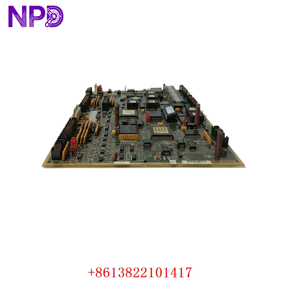
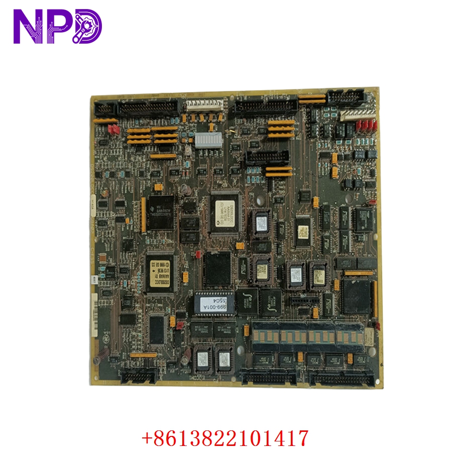
- Model: DS200LDCCH1AGA
- Brand: GE (General Electric – USA)
- Series: Mark V Speedtronic / Innovation Series Drive Architecture
- Core Function: Primary drive control and local area network (LAN) communication processor card for high-horsepower EX2000 and Innovation Series systems
- Product Type: LDCC LAN Drive Control Board
- Key Specs: Dual Microprocessor Architecture | 4x High-Speed DLAN Optical/Coaxial Links | Alphanumeric Diagnostic Display | Multi-Layer Backplane Header
- Processing Core: Dual-microprocessor design split between dedicated real-time drive-control loops and high-speed LAN data processing
- Network Interfaces:
- 2x High-speed DLAN (Drive Local Area Network) coaxial terminal lines
- 2x ARCNET / Genius network fiber-optic communication interfaces
- User Diagnostics: Onboard 1-line, 10-character alphanumeric LED display tracking system boots, diagnostic states, and trip codes
- Hardware Suffix Configuration:
- H1: Standard high-tier performance functionality block matrix
- A: First-generation circuit board design topology
- G: Factory-applied conformal coating layer for harsh industrial environments
- A: Group 1 functional revision status
- I/O Connectivity: 4x plug-in ribbon cable ports interfacing directly with peripheral bridge, gate drive, and power terminal boards
- Memory Subsystem: Removable EEPROM socket modules containing site-specific drive tuning parameters and system operating configuration files
- Signal Dampening: Onboard hardware jumper arrays for matching transmission network impedance and loop termination settings
Application Scenarios & Engineering Pitfalls
The On-Site Reality
In large-scale continuous process setups—such as a power station gas turbine starter, a massive paper mill main section line, or a steel strip rolling mill—the drive control board is the brain of the machinery. The DS200LDCCH1AGA handles the real-time mathematics for torque control, speed profiles, and system synchronization, while simultaneously passing critical telemetry back to the overarching Mark V control system. When an LDCC card fails or its flash memory degrades due to thermal stress, the entire drive shuts down instantly, freezing the process line. Because these vintage GE boards are long out of production and highly sensitive to firmware revisions, having a verified, properly coated replacement ready to run is vital to avoid extended, multi-week plant outages.
Typical Deployment Scenarios
- Power Generation – EX2000 Generator Excitation Systems
Manages real-time field-current regulation loops and handles high-speed communications back to the main Speedtronic turbine control panel.
- Heavy Heavy Industry – Coordinated Steel Rolling Mill Section Drives
Synchronizes high-torque multi-drive arrays to ensure uniform material thickness, demanding sub-millisecond data loop updates.
- Pulp & Paper – High-Output Primary Paper Machine Sectional Drives
Routes precise speed-matching variables down the machinery line to prevent continuous web snaps during acceleration.
- Oil & Gas – High-Horsepower Compressor Prime Mover Systems
Monitors internal gate driver feedback loops and isolates control logic lanes from high-voltage transients in critical pumping stations.
Plant Survival Case Study: Steel Mill Main Roll Failure Resolved
- Background: A major steel mill was operating a continuous hot-strip rolling mill section driven by a legacy GE Innovation Series drive cluster. The core control framework within the primary inverter cabinet relied on a DS200LDCCH1AGA LAN drive control board.
- The Problem: During an exceptionally high electrical load transition phase, an auxiliary cooling fan failure inside the drive cabinet caused temperatures to spike dramatically. The extreme thermal stress caused a localized breakdown within the data-bus gating components on the active LDCC board. The drive dropped out on a hard “LAN Control Link Failure” alarm, halting the entire rolling line and trapping a hot steel slab mid-process. The mill was losing an estimated $35,000 per hour, and standard OEM distribution networks listed the board as obsolete with no available stock.
- The Solution: The automation project supervisor bypassed standard procurement blockages by contacting our support group directly. We quickly pulled a clean DS200LDCCH1AGA card from our climate-controlled warehouse reserves, ran it through our comprehensive multi-channel signal injection validation and communication loop tests, and shipped it out via priority air freight within 4 hours.
- The Result: The replacement hardware arrived at the plant gate early the next morning. The maintenance team transferred the site-specific EEPROM chips from the faulty board, mounted the new module on its rack standoffs, and re-seated the ribbon connections. The drive initialized perfectly on the first boot, allowing the mill to clear the line and resume full production before the afternoon shift.
Compatible Replacement Models
When working with vintage GE Speedtronic and drive components, matching the precise character groups within the alphanumeric suffix is critical to prevent backplane communication errors or firmware rejections.
| Original Part Number | Alternative Model | Compatibility Level | Key Differences / Structural Variances | Required On-Site Modification Steps | Cost Variance |
| DS200LDCCH1AGA | DS200LDCCH1AGA Exact Match | ✅ Drop-in Replacement | Exact hardware build and engineering lineage match; contains standard firmware compatibility and identical connector positions. | Direct physical swap. Transfer your custom EEPROM configuration chips and match all jumper settings. | Baseline Cost |
| DS200LDCCH1AGA | DS200LDCCH1BGA | ⚠️ Software Compatible | Revision Group B architecture. Features upgraded internal logic arrays but remains functional layout compatible. | Requires verifying that your existing drive system firmware version recognizes the updated Revision B block. | +15% |
| DS200LDCCH1AGA | DS200SDCCF1A | ❌ Hardware Incompatible | Drive control board belonging to an alternative generation framework. Uses different backplane register structures. | Do not attempt. The physical connectors, communication protocols, and register maps do not match the LDCC layout. | -25% |
Quality Assurance & Testing Standard Operating Procedure
To address the high-reliability demands of safety-critical manufacturing and excitation systems, every single GE control board undergoes a documented, multi-point functional verification process before being packaged and cleared for site shipment.
[Inbound Serialization Log] ➔ [Optical Microscopic Audit] ➔ [Power Rail Isolation Verification] ➔ [Dual-Processor Logic Emulation] ➔ [DLAN Communication Loop Test] 1. Inbound Traceability and Structural Screening
- Authenticity Profiling: Verifying the physical manufacturer nameplate, internal board traces, and manufacturing revision codes against GE’s industrial drive production history.
- Chassis Assessment: Detailed checking of the board edges, high-density backplane header rows, and ribbon cable connector sockets to ensure zero physical defects.
2. Optical Microscopic Solder Joint Audit
- Joint Analysis: High-magnification optical inspection of surface solder joints under digital microscopes, searching for cold joints, micro-fractures, or trace oxidation built up over extended storage.
- Coating Verification: Checking the integrity of the “G” code conformal coating layer to confirm full moisture and dust protection coverage across all components.
3. Galvanic Isolation Circuit Verification
- Insulation Resistance Execution: Using a specialized digital insulation tester to apply 500 V DC between the primary power trace lines and the chassis grounding plane tracks.
- Acceptance Threshold: The insulation barrier must measure above 10 MΩ to ensure absolute protection against field spikes bridging into the primary processing logic arrays.
4. Dual-Processor Logic Emulation
- The Testing Environment: The DS200LDCCH1AGA card is seated into a functional GE Mark V / Innovation Series testing rack framework linked to a simulated drive load matrix.
- Processor Diagnostic Check: We boot the card and monitor the onboard alphanumeric display panel to verify that the self-test sequence completes successfully without triggering internal processing faults.
- Parameters Transfer Check: Verifying the card’s ability to read and write data reliably across the socketed EEPROM interface channels.
5. DLAN Communication Loop Validation
- Data Transmission Audit: We run active communication loops across both the coaxial DLAN terminals and the fiber-optic network channels at full rated data transfer frequencies.
- Packet Drop Verification: Monitoring the network lines using digital test diagnostics to confirm zero frame dropouts, timing skew, or cross-channel trace noise.
Drive Control Board Field Troubleshooting Quick Reference
❗ SAFETY FIRST: Disconnect and lock out all main three-phase power feed lines coming into the drive or excitation cabinet before opening doors or touching internal control components. Verify that all internal DC bus capacitors have completely discharged to 0 V using a verified, high-voltage voltmeter.
Q: The drive fails to boot, and the onboard 10-character alphanumeric display on the LDCC card stays dark, while adjacent rack components show active power indicators.
A: Correlation: High. This symptom typically points to a blown input protection circuit or a failure within the internal multi-rail switching power supply block on the DS200LDCCH1AGA card.
- Safely isolate the power lines and remove the card from its housing rack.
- Use a digital multimeter to verify that the primary DC operating voltages are reaching the card via the main backplane or power connector block.
- If input power is present but the display and status LEDs remain dead, the board’s internal power processing path is damaged. Swap out the card for a verified spare.
Q: The drive boots up but immediately trips out on a hard “EEPROM Configuration Mismatch” or “Parameter Read Error” alarm code.
A: Correlation: High (Software/Configuration data missing). The new or existing LDCC card cannot read your specific machine tuning variables from the socketed EEPROM modules.
- Shut down the drive panel and verify that you have transferred the original, site-specific EEPROM chips from your old board into the correct sockets on the replacement card.
- Check the alignment of the chips inside the sockets. Ensure that no pins are bent beneath the chip bodies and that the chip orientation markers line up with the socket indicators.
- Clean any dust or debris out of the socket frames using a residue-free electrical contact cleaner. If the chips are seated correctly but the fault persists, the configuration data may be corrupted, requiring a reload from your archived project backups.
Q: The drive runs normally under manual control, but intermittently loses connection with the central control room, logging a continuous “DLAN Coaxial Link Failure” message.
A: Correlation: High. This problem indicates that the transient noise filtering arrays or grounding paths on the LDCC card have degraded over time, or the network line configuration jumpers are set incorrectly.
- Inspect the onboard hardware jumper positions on the replacement card. Ensure they match the exact impedance matching and termination settings used on the original board you pulled from service.
- Check the BNC coaxial connector sockets for any signs of physical wear, oxidation, or loose center pins.
- If the jumpers match your network specifications and the cables are sound, the internal line transceiver chips on the card have degraded. Replace the board to restore reliable communication.
❗ Critical Field Installation Checklist for Plant Technicians
- Transfer Site-Specific EEPROMs: Never apply power to a replacement LDCC board using factory-default chips. The DS200LDCCH1AGA stores your specific motor parameters, tuning gains, and network configurations on removable EEPROM chips. You must carefully swap these chips from your old board into the exact matching sockets on the replacement card before powering up the drive.
- Duplicate All Hardware Jumpers: Before sliding the replacement card onto its rack mounts, walk through every single hardware jumper position on the board surface. Cross-reference them against the layout of the card you are replacing. Incorrect jumper settings can lead to network address conflicts, termination issues, or unexpected drive behavior during commissioning.
- Ensure Secure Ribbon Ribbon Seating: When reconnecting the multi-pin ribbon cables between the LDCC card and peripheral boards, push the connectors fully into their sockets until the retaining clips snap shut. Loose or slightly crooked ribbon connections can inject noise or cause intermittent logic faults that are extremely difficult to isolate during troubleshooting.