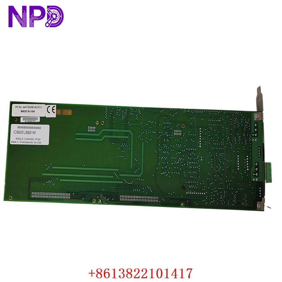

Description
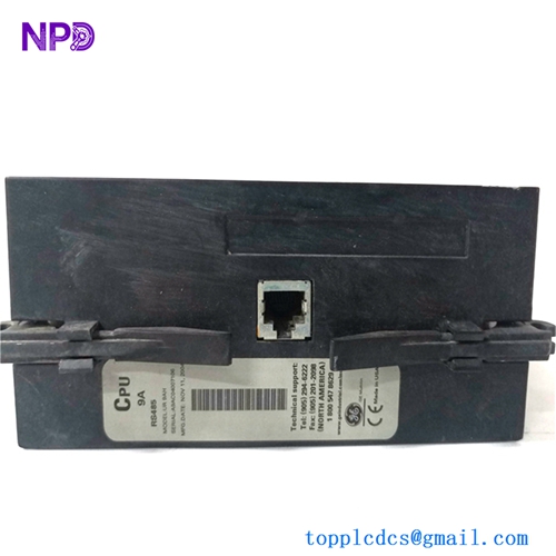
- Model: IC660ELB921M
- Brand: GE Fanuc (General Electric)
- Series: Genius I/O
- Core Function: Provides high-performance analog input and output signal conversion for distributed industrial control systems.
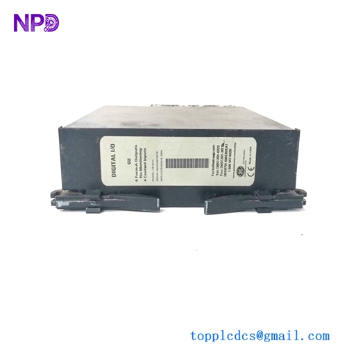
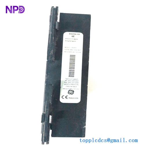
- Product Type: Genius I/O Block (Analog I/O)
- Key Specs: 4 Analog Inputs / 2 Analog Outputs | 24 V DC Power Input | Genius Bus Communication
- Input Channels: 4 Analog Inputs, independently configurable for voltage (0 to 10 V, -10 to +10 V) or current (4 to 20 mA).
- Output Channels: 2 Analog Outputs, configurable for voltage or current loop.
- Resolution: 12-bit conversion for high-precision process control.
- Communication Interface: Dual-redundant Genius Bus (Serial link) for high-speed, noise-immune data exchange.
- Power Requirements: 24 V DC nominal, isolated from the I/O signal logic.
- Diagnostic Features: Built-in support for “Loss of Communication” and “Loss of Signal” detection reporting.
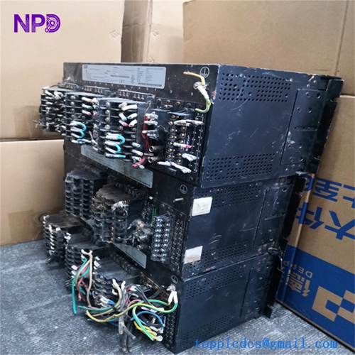
- Enclosure: Industrial-grade, modular design suitable for DIN rail or panel mounting.

GE IC660ELB921M
GE IC660ELB921M
GE IC660ELB921M
Engineering & Application Context
The On-Site Reality
The IC660ELB921M is a staple of the legacy GE Genius I/O series, still widely used in power generation, water treatment, and metal processing. It acts as a distributed node, allowing the PLC to collect analog sensor data and control process valves or drives over a single bus cable, reducing the need for massive amounts of point-to-point wiring. When these blocks fail, the “loss of analog feedback” can trigger a process trip, requiring an immediate replacement that matches your existing bus configuration.
Typical Deployment Scenarios
- Process Instrumentation: Interfacing with pressure transmitters, flow meters, and level sensors.
- Valve Control: Driving proportional valves or actuators where precise positioning is required via a 4 to 20 mA signal.
- Distributed Control: Reducing cabinet size by mounting the I/O block close to the field devices, minimizing signal degradation over long wire runs.
Troubleshooting Quick Reference
❗ SAFETY FIRST: Always verify the I/O block’s power state and bus status before removing the terminal strip.
- Status LED Patterns:
- Bus OK LED (Green): Indicates healthy communication with the Genius bus controller. If this is off or flashing, check the bus cable terminations (120-ohm resistors) and bus polarity.
- I/O Fault LED (Red): Indicates a localized failure within the block’s channel logic or a “Loss of Signal” (e.g., open loop detection on a 4 to 20 mA channel).
- Signal Loop Testing: If a channel is reading a constant maximum/minimum, use a signal generator to inject a known value (12 mA or 5 V). If the block reads this value correctly, the issue is likely your field sensor or wiring, not the block itself.
- Grounding Errors: The Genius I/O block is sensitive to ground loops. Ensure that the signal common and the power supply common are handled according to your system’s grounding philosophy, or you may observe “jittery” analog readings.
Migration & Replacement Strategy
- Firmware Versioning: Ensure the replacement unit’s firmware revision is compatible with your existing Genius Bus controller software.
- Address Mapping: Ensure the new block is set to the same physical Genius bus address as the old one (via the rotary switches or configuration software) to prevent system-wide address conflicts.
- Connector Integrity: The terminal blocks for the Genius series are prone to oxidation in high-humidity environments. If you replace the unit, inspect the terminal strip contacts for any signs of pitting or corrosion.