
Description
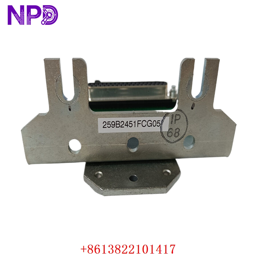
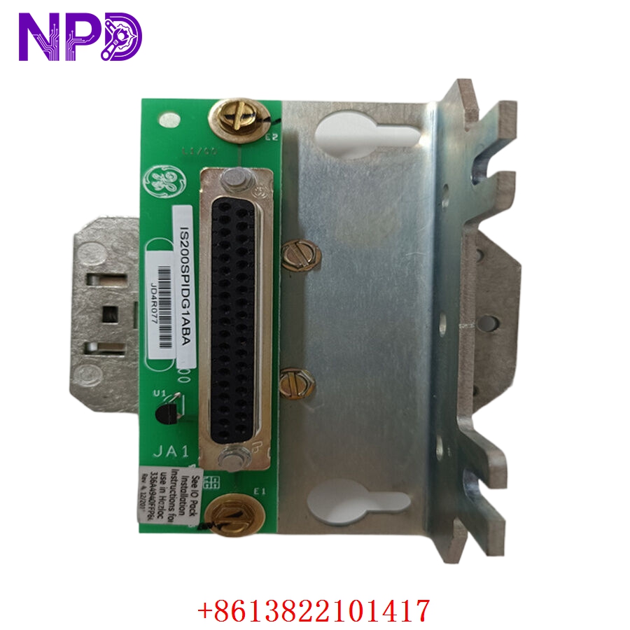
The GE IS200SPIDG1ABA is a specialized Pulse Rate Input (SPI) terminal board designed for the GE Mark VIe control system. It is engineered to provide high-accuracy monitoring of speed and frequency signals from field instruments, such as magnetic speed pickups or pulse-generating flow meters. This board acts as a crucial interface for rotating equipment, ensuring that the control system receives precise feedback for turbine speed control and synchronization.
Technical Specifications
| Parameter | Detail |
| Model | IS200SPIDG1ABA |
| Manufacturer | General Electric (GE) |
| System Compatibility | Mark VIe Turbine Control System |
| Function | Pulse Rate/Frequency Signal Input |
| I/O Capability | High-accuracy pulse counting |
| Mounting | Cabinet Backplane |
| Operating Temperature | 0°C to 60°C |
Fields of Application
The IS200SPIDG1ABA is primarily utilized in power generation and large-scale mechanical drive facilities. Its key fields of application include:
- Gas and Steam Turbines: Providing critical turbine shaft speed feedback to the Mark VIe controllers.
- Synchronous Generators: Monitoring frequency for grid synchronization.
- Centrifugal Compressors: Managing overspeed protection and speed-dependent control loops.
- Flow Measurement: Calculating volumetric flow rates from high-frequency pulse transmitters.
Product Introduction
The SPIDG1ABA board serves as the input stage for speed and frequency signals. It is designed to filter out electromagnetic noise and convert raw, oscillating pulses into clean digital data that the control processor can utilize for high-speed logic. Given its role in critical safety functions like overspeed protection, the board is built with high-reliability circuitry to ensure that signals are captured without jitter or loss.
Product Use Instructions
To integrate this board into a Mark VIe system:
- Ensure the control cabinet is de-energized and follows site LOTO procedures.
- Carefully seat the board into the designated I/O terminal position on the cabinet backplane.
- Secure the board using the integrated mounting hardware.
- Terminate field wiring (typically from speed sensors) to the appropriate screw terminals on the board faceplate. Ensure signal shields are properly grounded to the cabinet’s grounding bus to prevent signal degradation.
- Connect the I/O pack to the board according to the specific turbine control cabinet wiring schematics.
- Once powered, configure the pulse input scaling (pulses per revolution) in the Mark VIe HMI/ToolboxST software to ensure speed values are accurately reported.
Product Use Precautions
The board is sensitive to voltage spikes on the input lines; always verify that your speed sensors do not output voltages exceeding the board’s specifications. Handle the board using proper ESD protocols to avoid damaging the sensitive input circuitry. Never attempt to “hot-swap” the board unless the Mark VIe configuration and base hardware explicitly support live removal. Keep the cabinet interior clean, as conductive debris can bridge the input terminals and cause erroneous speed readings.
Frequently Asked Questions (Q&A)
Q: What is the primary difference between the SPID board and a standard analog input?
A: The SPID is optimized specifically for processing square-wave or sinusoidal frequency signals, whereas analog inputs are designed for voltage or current loops (e.g., 4-20mA).
Q: How can I verify that the board is receiving a signal?
A: You can monitor the “Speed Feedback” or “Frequency Input” values within the ToolboxST diagnostics. Additionally, many SPID boards feature local status LEDs that indicate signal presence.
Q: Is this board repairable?
A: No, due to the high-density nature of the circuitry and its role in critical control, these boards are treated as “Replace-Only” components.
Product Operation Methods
The board functions by acting as a hardware-level counter. It constantly monitors the frequency of incoming pulses. As the shaft rotates, the magnetic pickup generates a voltage pulse; the SPIDG1ABA board detects each pulse and passes this data to the I/O pack. The system calculates the time between these pulses to determine the speed in real-time. During operation, this loop is entirely automatic and provides the control processor with the sub-millisecond feedback required for stable turbine speed regulation.