
Description
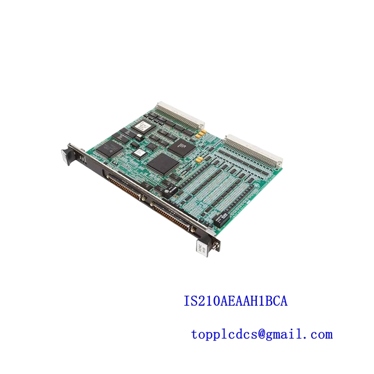
- Model: GE IS200TBCIH2CAA
- Internal Reference: MRP604466
- Brand: GE (General Electric)
- Series: Mark VI / Speedtronic Turbine Control System
- Core Function: Processes discrete contact input signals for turbine and process control logic execution
- Product Type: Contact Input Terminal Board / I/O Interface Module
- Key Specs: 24 V DC signal interface, multi-channel discrete input processing, redundant system compatible architecture
- Input Type: Dry contact / discrete signal input
- System Compatibility: GE Mark VI / Speedtronic control system
- Channel Configuration: Multi-channel digital input processing (system dependent mapping)
- Input Voltage: 24 V DC nominal
- Isolation: Opto-isolated input channels (industrial noise protection design)
- Backplane Interface: Rack-mounted terminal board connection
- Signal Processing: Real-time turbine control logic input acquisition
- Communication Path: Through Mark VI controller backplane architecture
- Operating Temperature: 0 °C to 60 °C
- Storage Temperature: -40 °C to 85 °C
- Humidity Range: 5%–95% non-condensing
- Mounting Type: Rack-based turbine control cabinet installation
- EMC Protection: Industrial-grade noise suppression design
- Weight: Approx. 0.8–1.2 kg (variant dependent)
- Application Environment: Power generation / petrochemical / heavy industry turbine systems
Installation & Configuration Guide
Stage 1: Pre-Installation Preparation (Approx. 15–20 minutes)
⚠️ Field rule: never touch Mark VI I/O boards without full power isolation.
- Confirm turbine is in safe shutdown state
- Transfer control to standby or manual mode
- Disconnect control cabinet power and UPS supply
- Wait minimum 10 minutes for full discharge
Tools required:
- Anti-static wrist strap
- Fluke 115 multimeter (for 24 V DC verification)
- Label tags for wiring identification
- Camera for rack documentation
- Torque screwdriver set
Backup actions:
- Save Mark VI configuration through engineering workstation
- Record I/O mapping table
- Photograph terminal board layout
- Confirm redundancy status (if TMR system is used)
Stage 2: Removal of Existing Board (Approx. 10–15 minutes)
- Confirm zero voltage on input terminals
- Disconnect all field wiring carefully
- Label each wire before removal
- Release board locking mechanism from rack
- Pull board straight out to avoid backplane damage
⚠️ Practical note:
In Mark VI systems, many “board failures” are actually loose terminal connections caused by vibration over long runtime.