Description
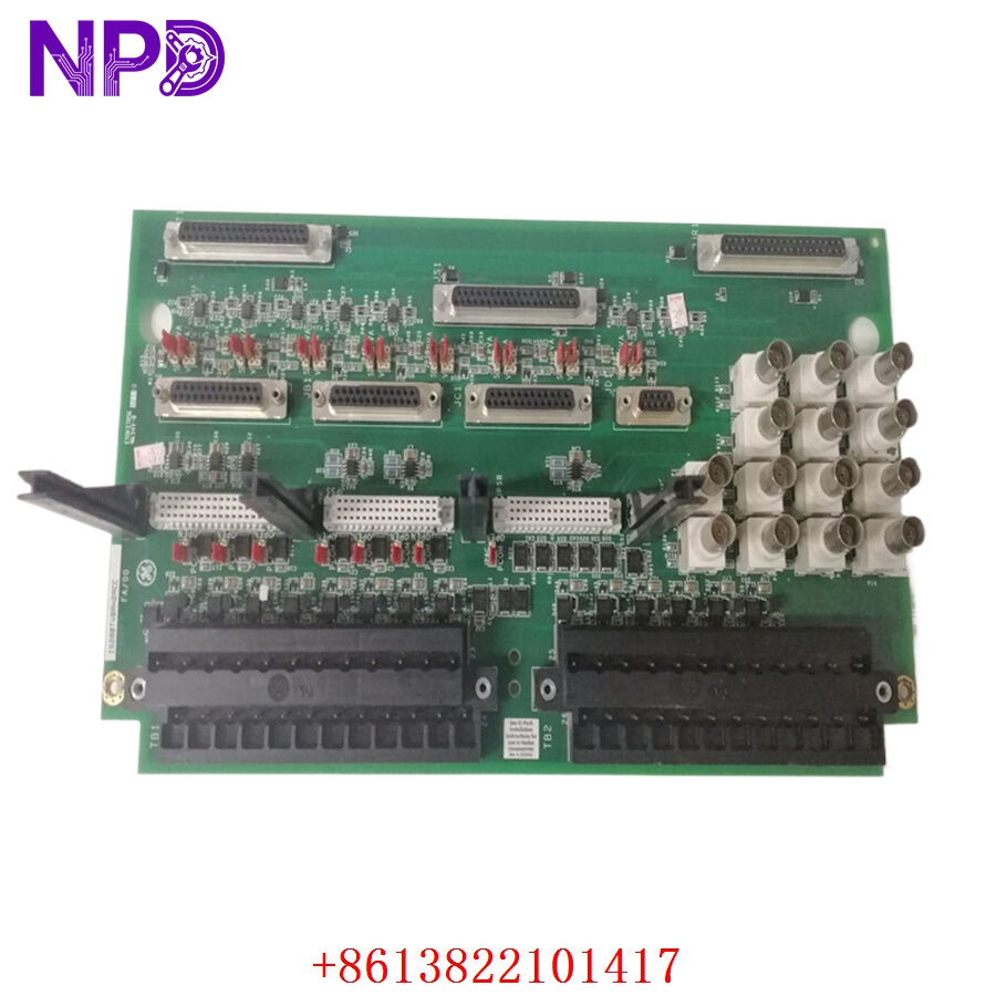
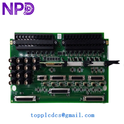
- Model: GE MRP646218 IS200TVBAH2ACC
- Brand: GE (General Electric)
- Series: Mark VI Speedtronic Turbine Control Platform
- Core Function: Interfaces vibration monitoring signals with turbine control system
- Product Type: Terminal Board / Vibration Interface Module
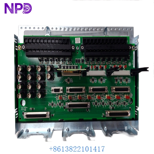
- Key Specs: Mark VI compatible, vibration signal termination, rack-mounted design
- Module Type: Turbine vibration terminal board
- Series Compatibility: GE Mark VI Speedtronic system
- Board Reference: IS200TVBAH2ACC
- Associated Part Number: MRP646218
- Function: Vibration signal termination and distribution
- Mounting Method: Control cabinet rack installation
- Signal Type: Analog vibration monitoring interface
- Communication Path: Interfaces with Mark VI I/O architecture
- Connector Type: Industrial terminal block connectors
- Application Area: Gas turbine and steam turbine control systems
- Operating Environment: Industrial turbine control cabinets
- Power Source: Backplane/system powered architecture
- System Integration: Compatible with Mark VI vibration protection logic
- Typical Usage: Turbine bearing monitoring and trip protection circuits
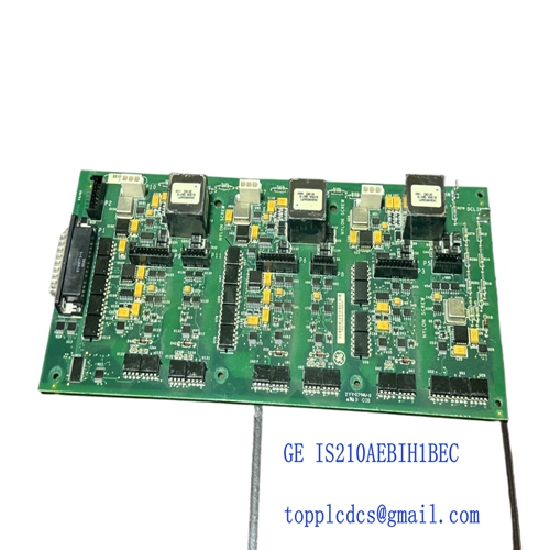
GE MRP646218 IS200TVBAH2ACC
GE MRP646218 IS200TVBAH2ACC
GE IS200TVBAH2ACC
GE IS200TVBAH2ACC
Installation & Configuration Guide
Stage 1: Pre-Installation Preparation (Approx. 15–20 minutes)
⚠️ Before replacing any vibration-related board, place the turbine control system into approved maintenance condition.
- Notify operations and turbine maintenance teams
- Transfer machine to safe shutdown state
- Isolate cabinet power supplies
- Wait minimum 5–10 minutes before handling electronics
Required tools:
- Anti-static wrist strap
- Fluke 115 multimeter
- Terminal screwdriver set
- Label markers
- Engineering laptop with Mark VI diagnostic tools
Backup recommendations:
- Photograph terminal wiring layout
- Record cable labels and terminal positions
- Save current alarm and vibration trend data
- Verify cabinet grounding condition
One thing experienced turbine technicians always do:
Take close-up photos of terminal wiring before disconnecting anything. Vibration channels can become confusing surprisingly fast during reassembly.
Stage 2: Removal of Existing Module (Approx. 10 minutes)
- Confirm cabinet power isolation
- Label all field vibration cables
- Disconnect terminal wiring carefully
- Remove mounting hardware
- Extract terminal board slowly from rack position
⚠️ Important:
Do not pull signal wiring aggressively. Vibration monitoring cables are sensitive to shielding and grounding integrity.