Description
Product Parameters
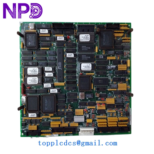
- Model Number: DS200SDCCG1AGD (Compatible with DS215SDCCG1AZZ01B)
- Series: GE Mark V Speedtronic
- Functional Description: Drive Control Card (SDCC)
- Microprocessors: 80196 (Motor Control), 80186 (Drive Control), and 80C196 (LAN Control)
- I/O Configuration: On-board jumpers, DIP switches, and 10+ LED diagnostic indicators
- Country of Origin: USA
- Weight: 1.25 lbs (0.57 kg)
- Dimensions: 11.5 in x 7.5 in x 1.0 in (29.2 cm x 19.1 cm x 2.5 cm) The DS200SDCCG1AGD serves as the primary controller for GE Mark V drive systems, integrating three high-speed microprocessors to manage localized motor control, overall drive functions, and LAN communications simultaneously. This card is engineered for real-time processing of I/O signals and drive logic, featuring a modular architecture that supports field-programmable logic via EPROM chips and offers extensive diagnostics through its integrated LED array and test points.
GE DS200SDCCG1AGD DS215SDCCG1AZZ01B
GE DS200SDCCG1AGD DS215SDCCG1AZZ01B
Model Comparison
The DS200SDCCG1AGD is a direct iteration of the SDCC family, whereas the DS215SDCCG1AZZ01B is a later revision often associated with updated firmware or component longevity improvements. While they share the same physical footprint and fundamental logic, the “215” series generally includes hardware enhancements for better EMI shielding or updated surface-mount components compared to the “200” series. The “G1A” suffix on the 200 model denotes a specific group configuration that must match the drive’s software requirements, while the “ZZ01B” suffix on the 215 model often indicates a customized or updated software bundle pre-loaded onto the board’s EEPROMs.
Operation Tips
- Static Safety: This board is highly sensitive to Electrostatic Discharge (ESD); always wear a grounded wrist strap and handle the board only by its edges.
- EPROM Transfer: When replacing an old unit, ensure you transfer the original configuration EPROMs and BIOS chips to the new board unless the new unit is pre-configured.
- Jumper Calibration: Before powering up, verify that all hardware jumpers and DIP switch positions on the new board exactly match the settings of the board being replaced to avoid drive faults.
- Diagnostic Check: Upon initialization, observe the LED sequence; a steady blinking or specific pattern (as defined in the Mark V manual) confirms the processors have successfully booted and are communicating with the LAN.