
Description
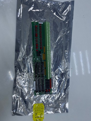
The GE DS200TBQCG1ABB is a high-performance Analog Input Termination Board designed for the Speedtronic Mark V Gas Turbine Control System. It serves as the primary physical interface for field-wired analog signals, facilitating the connection between external sensors (such as pressure transmitters, flow meters, and LVDTs) and the control processors. The board is engineered to provide high-speed data acquisition with integrated signal conditioning and noise suppression to ensure the integrity of critical turbine data.
- System Compatibility: GE Speedtronic Mark V (R, S, and T Cores)
- Input Channels: Supports up to 15 analog input channels
- Signal Types: 4-20 mA current loops, ±10V DC, and 0-5V DC inputs
- Termination: Dual terminal blocks with 36 silver-plated screw terminals each
- Isolation: Galvanic isolation and surge protection per channel
- Configuration: Onboard Berg jumpers for hardware scaling and signal type selection
- Redundancy: Supports Simplex and TMR (Triple Modular Redundant) architectures
Product Datasheet
| Feature | Specification |
|---|---|
| Model | GE DS200TBQCG1ABB |
| Series | Mark V Speedtronic |
| Dimensions | 280 x 125 x 40 mm |
| Weight | 0.65 kg |
| Country of Origin | USA |
| Connector Type | Screw Terminal / Ribbon Cable Headers |
| Revision | ABB (Enhanced revision for high reliability) |
Application Fields
This termination board is essential for the monitoring and control of heavy-duty rotating equipment in the following sectors:
- Power Generation: Interfacing fuel flow transmitters and hydraulic valve positioners in gas turbines.
- Oil & Gas: Used in centrifugal compressor control systems for pressure and temperature monitoring.
- Industrial Plants: Real-time data acquisition for large-scale steam turbine governors.
- Combined Cycle Plants: Integration into Heat Recovery Steam Generator (HRSG) control loops.
Product Instructions
- Safety Protocol: Ensure the Mark V control panel is powered down and locked out before installation. Follow all plant-specific ESD (Electrostatic Discharge) safety measures.
- Mounting: Install the board onto the designated standoffs within the <R>, <S>, or <T> core. Ensure the board is physically secure to provide proper electrical grounding through the mounting points.
- Jumper Setting: Configure the onboard jumpers (e.g., JP1 through JP15) to match the input signal type (Current vs. Voltage) for each specific field sensor as outlined in the Mark V application manual.
- Wiring: Connect field wires to the screw terminals. Use shielded twisted-pair cabling for all analog signals and ensure shields are grounded at the terminal board end only.
- Cabling: Attach the 2R, 2S, or 2T ribbon cables to the headers on the TBQC board to transmit the conditioned signals to the I/O processor boards.
Q&A – Common Questions
Q1: What does the “ABB” suffix represent? A1: The suffix denotes the specific hardware revision. “ABB” indicates a version of the board that has undergone specific component updates and layout optimizations for better performance compared to the base “A” version.
Q2: How do I troubleshoot an inaccurate analog reading on a specific channel? A2: First, verify the jumper settings for that channel. Next, measure the raw signal at the screw terminals with a calibrated multimeter. If the terminal voltage/current is correct but the HMI reading is wrong, check the ribbon cable and the downstream I/O processor board.
Q3: Is this board compatible with both Simplex and TMR systems? A3: Yes. The DS200TBQCG1ABB is designed to operate in both Simplex (single-core) and TMR (triple-core) Mark V configurations. In TMR systems, the signal is typically fanned out to three separate processors.
Related Product Recommendations
- GE DS200TCDAG1B | Digital I/O Board
- GE DS200TCQCG1A | Analog Configuration Board
- GE DS200STCAG1A | Signal Terminal Card
- GE DS200SDCCG1A | Drive Control Card
- GE DS200PTBAG1A | Power Terminal Board