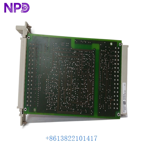
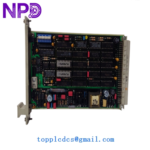
Description
- Model: F7553
- Brand: HIMA (Germany)
- Series: H41q / H51q Systems
- Core Function: 4-channel safety-related analog input (4-20 mA / 0-20 mA)
- Type: Analog Input Module (Safety)
- Key Specs: 12-bit resolution, galvanically isolated, SIL 3 rated
- Number of Channels: 4 (Safe isolation)
- Input Range: 0/4…20 mA (Scalable via software)
- Input Resistance: Approximately 250 Ω
- Resolution: 12-bit (Provides high granularity for process variables)
- Safety Integrity: Suitable for up to SIL 3 applications
- Measurement Error: < 0.2% at 25°C
- Internal Power Consumption: 5 V: 120 mA | 24 V: 150 mA
- Diagnostics: Comprehensive self-test including A/D converter checks and cross-talk monitoring
- Galvanic Isolation: Standard isolation between field circuits and system bus
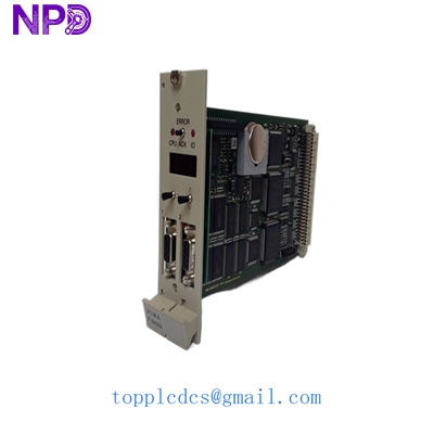
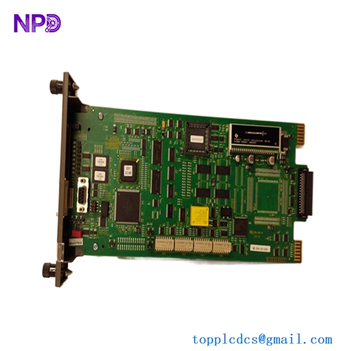
HIMA F7553
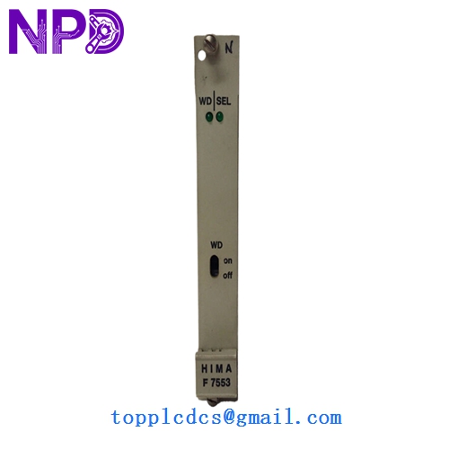
HIMA F7553
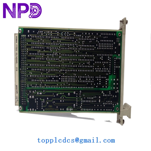
HIMA F7553
Installation & Configuration Guide
Phase 1: Pre-Installation (Preparation: 15 minutes)
⚠️ Critical Warning: This module handles critical process variables. An incorrect reading can cause a trip or, worse, fail to trip during a dangerous condition.
- Bypass Procedures: Ensure the specific safety loops (e.g., Boiler Pressure, Tank Level) are in “Bypass” or “Maintenance Mode” within the SIS to prevent a false trip.
- Jumper Configuration: On the F7553, check for any mechanical jumpers or DIP switches that set the input type (e.g., 0-20 mA vs 4-20 mA). They must match the old board exactly.
- ESD Protocol: These boards use high-precision A/D converters that are highly vulnerable to static damage. Wear a grounded wrist strap.
Phase 2: Removal (Step-by-Step)
- Safety Shutdown: If the rack is not hot-swap capable (check your specific H41q/H51q configuration), power down the sub-rack.
- Unfasten: Loosen the top and bottom screws on the module front plate.
- Ejection: Use the handles to pull the board straight out. Note: The F7553 is a heavy-duty PCB; ensure you support the bottom as it clears the rack guides.
- Connector Inspection: Check the backplane connector for any dust or bent pins before proceeding.
Phase 3: Installation & Calibration
- Insertion: Slide the new module in until the front plate is flush. Tighten the screws to ensure a proper ground connection to the rack frame.
- Initialization: Power up the rack. The “RUN” (Green) LED should illuminate.
- Signal Calibration:
- Use a signal generator (like a Fluke 789) to inject a 4 mA and 20 mA signal into each channel.
- Verify the values in the ELOP II or SILworX software match the injected values.
- Final Check: Clear all diagnostic alarms and remove the bypasses once the loop is verified.
Customer Cases & Industry Applications
Case 1: Petrochemical Refining – Level Control A refinery in Southeast Asia reported a “Bad Value” fault on a critical reactor level sensor. The fault was traced to a degraded A/D converter on the F7553 module. A system trip would have cost the plant nearly $1.2 million in flare-off and restart expenses. We provided a New Surplus module via priority overnight shipping. The board was replaced during a 20-minute maintenance window, and the plant stayed online.
Case 2: Power Generation – Steam Pressure Monitoring An aging coal-fired power plant used HIMA H51q systems for burner management. They were experiencing “drift” in their analog readings, leading to nuisance alarms. By replacing their old, heat-stressed cards with our New Surplus F7553 units, the signal stability was restored to original factory tolerances. The I&E supervisor noted, “The New Surplus boards gave us another 10 years of life on a system the OEM told us to scrap.”
Frequently Asked Questions (FAQ)
Q: Can I replace an F7553 with an F7553A? A: Generally, yes. The “A” version is a later revision. However, you must check the firmware version of your CPU. Older HIMA processors may require a minimum firmware level to recognize the “A” revision’s enhanced diagnostics.
Q: Why is my “ERR” LED blinking after installation? A: This is most commonly a “Line Monitored” fault. The F7553 looks for a live 4 mA signal. If your transmitter is not powered or the loop is open, the module will report a fault. Verify the loop current with a multimeter first.
Q: How do I know these aren’t “Refurbished” boards? A: Refurbished HIMA boards often show signs of “re-capping” (new capacitors) or have yellowed PCB edges from heat exposure. Our New Surplus units have clean, green solder masks, original factory labeling, and no “hours-run” marks on the edge connectors.
Q: Is calibration required after replacement? A: While the F7553 is factory-calibrated, in a SIL 3 environment, we always recommend a “Loop Verification.” Injecting a known current and checking the HMI value ensures that the entire signal path—from the terminal block to the software—is accurate.