
Description
🔍 Product Overview
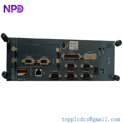
The Lyngso Marine IOM 402 (Part Number: 271.149 244) is a highly reliable industrial Input-Output module designed for marine automation, vessel monitoring, and integrated alarm systems. Developed under the Sam Electronics / Lyngso Marine infrastructure, this module serves as a decentralized node that interfaces physical field signals directly with the vessel’s primary distributed control system (DCS) or main bridge workstation. Built with marine-certified components, it provides exceptional noise isolation and high-density channel monitoring to guarantee structural signal integrity under the continuous vibrations and harsh electromagnetic conditions of marine engine rooms.

⚙️ Technical Parameters & Specifications
- Model Number: IOM 402
- Part Number (P/N): 271.149 244 (often written as 271149 244)
- Associated Brand: Lyngso Marine / Sam Electronics / Wärtsilä Automation
- Module Type: High-Density Input-Output Module
- Dimensions: 170 mm x 125 mm x 50 mm
- Weight: 0.62 kg
- Country of Origin: Denmark / Germany
🚀 Application Areas
- Integrated Shipboard Automation Systems (IAS): Gathering status points and sensor data from auxiliary ship systems.
- Engine Room Monitoring Consoles: Processing temperatures, pressures, and digital switch states from propulsion and generator setups.
- Marine Alarm Monitoring Systems (AMS): Operating as a dedicated I/O drop for high-reliability machinery fault tracking.
- Ballast and Cargo Handling Subsystems: Driving field relay outputs and monitoring valve position feedbacks.
📖 Product Usage Instructions
The IOM 402 module is designed for flush mounting on standard TS35 DIN rails inside specialized field termination cabinets or console chassis plates. Observe standard anti-static handling (ESD) measures when inserting or handling the unit. Route the incoming digital and analog instrumentation cables separately from high-voltage motor feeders to minimize electrical noise. Ensure all pluggable terminal blocks are securely snapped and the locking mechanism is engaged to prevent field separation from vessel vibration.
🌐 Communication Configuration Steps
- IP Address / Network Setup: Access the system topology map through the Lyngso engineering configuration workstation. Assign a static IP address or specific network node ID to the module that coordinates with the vessel’s automated machinery network layer.
- Station Number / Node Identity: Set the specific station node identity using the physical binary dip-switches located under the module’s protective face cover, or push the identification registers down via the central system commissioning software.
- Baud Rate / Sync Speed: The module’s fieldbus transceivers are engineered with auto-adaptation algorithms, automatically synchronizing to the standard backbone frequency (such as 250 kbps for CAN networks or standard 10/100 Mbps for industrial Ethernet lines) depending on the configuration carrier.
⚡ Power-Up & Commissioning Flow
- Chassis Terminal Inspection: Verify that the field sensor loops are correctly wired to their corresponding channel numbers and that the ground trace is properly clamped.
- Power Input Check: Confirm that the auxiliary distribution circuit is providing a stable, nominal 24V DC supply to the primary power terminal ports.
- Boot Initialization: Flip on the control circuit breaker. Watch the front face indicators; the primary power LED should stay lit solid green, while the system execution LED flashes momentarily during self-test sequences.
- Signal Transmission Test: Induce a dry-contact switch change in the field and confirm that the corresponding channel LED on the IOM 402 changes state and updates the variable register on the bridge console HMI instantly.
✅ Initial Operation Checklist
- Is the internal chassis grounding clip making clear, bare-metal contact with the panel’s DIN rail backplane?
- Have the address dip-switches been checked against the master electrical print project drawing?
- Are the primary and redundant communication bus wires connected tightly to ensure fault-tolerant data routing?
- Does the main diagnostic screen show a healthy, active connection status for node 271.149 244?
❓ Common Questions (Q&A)
Q: What does a fast-flashing red or yellow error LED on the IOM 402 signal faceplate mean?
A: A rapid yellow or red flash typically points to a localized network communication timeout. The module is powered up and stable, but it is not receiving or replying to data frames from the master control unit. Check the network lines, terminating resistors, or address switch configurations.
Q: Can I replace an existing IOM 402 module while the central control panel remains powered?
A: While the network line structure is resilient, it is always best practice to isolate the specific 24V DC auxiliary power supply plug feeding the module before removing it. This safeguards internal processing components from accidental grounding spikes or pin short-circuits.
Q: How can I verify if an individual channel input circuit on the board is functioning if the HMI reports no signal?
A: Disconnect the field wires for that channel and jumper the terminals directly at the module face (for digital points) or apply a simulated milliamp signal. If the channel status LED on the IOM 402 board illuminates, the board logic is fully healthy, indicating that the fault lies in the external field sensor or cable run.