
Description
🌐 Product Overview
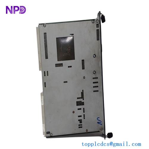
The Kongsberg RCU501 is a high-reliability, marine-certified Remote Controller Unit designed to act as a core distributed processing node within Kongsberg’s integrated automation and positioning networks. Built to manage real-time input/output (I/O) processing, data scanning, and localized control loops, this unit bridges the gap between field sensors and central operator workstations. Its hardened mechanical design allows it to be installed directly inside engine room cabinets or local control steering machinery spaces, providing high resistance to vibration, thermal stress, and electromagnetic interference.

⚙️ Technical Specifications
- Series: K-Chief / K-Pos Distributed Controller Infrastructure
- Dimensions: 265mm x 180mm x 120mm
- Weight: 4.10 kg
- Origin: Norway
- Processor Core: High-performance real-time industrial embedded microprocessor
- Supply Voltage: Dual-redundant 24V DC inputs (with integrated wide-tolerance voltage filtering)
- Backplane Interface: High-speed proprietary internal module bus for localized I/O expansion
- Network Interfaces: Redundant Ethernet channels configured for dual-ring topology networks
🚀 Application Fields
- Distributed Automation Systems (DAS): Localized monitoring and processing of tank levels, temperature arrays, and valve manifolds.
- Dynamic Positioning Interfacing: Serving as a reliable field interface unit that executes real-time propulsion and thruster commands.
- Engine Room Supervision: Distributed control node for auxiliary diesel networks, cooling systems, and air compressor setups.
- Safety Instrumented Systems (SIS): Implementing remote emergency shutdown (ESD) logic and critical safety interlock tracking.
📖 Product Instructions
- Enclosure Mount: Mount the RCU501 onto a rigid sub-panel within an IP-rated industrial enclosure. Ensure the chassis ground terminal is bonded via a low-impedance copper strap to the main cabinet earth ground bar.
- I/O Module Interfacing: Connect the remote I/O terminal extension modules to the dedicated internal bus connectors, verifying that all module locking tabs are securely snapped into position.
- Redundant Communication Network: Run separate network patches from LAN A and LAN B to separate physical network switches, maintaining physical separation of redundant lines to preserve network survivability.
✅ Initial Startup Checklist
- Check that the primary and secondary 24V DC power rails deliver correct voltages and are tied to separate battery backup banks.
- Verify that the node configuration DIP switches or rotary dials on the unit faceplate match the explicit station ID mapped in your automation topology layout.
- Power up the unit and confirm that the “OK” or “SYS” LED illuminates solid green and the communication “RX/TX” indicators display active flickering.
- Check from the main bridge engineering workstation that the RCU501 node registers as “Online” without flagging memory checksum or synchronization faults.
🛠️ Maintenance & Care
- Vibration Torque Audits: Re-torque all physical mounting bolts and pluggable wire terminal screws every six months to counteract persistent structural hull vibrations.
- Dust and Humidity Clearing: Wipe down the external casing during standard engine space overhauls with a dry, anti-static microfiber cloth to clear away oily film or salt spray traces.
- Battery Replacement: Track the status of the internal clock and volatile memory backup battery through your system diagnostic screen, replacing it during a scheduled port stay if a low-voltage warning surfaces.
⚠️ Safety Precautions
- Avoid Live Component Adjustments: Never extract or insert any internal interface cards or ribbon jumpers while the auxiliary power line is active.
- Redundancy Isolation Rules: When performing hardware diagnostics, never isolate both network channels simultaneously while the vessel is underway or using remote automated maneuvering modes.
- Electrostatic Grounding Protection: Utilize a certified ESD wrist strap when handling exposed terminal slots or interface headers to prevent static charges from breaking down internal logic arrays.
🔍 Troubleshooting & FAQ
- Q: The front panel “FAIL” light is lit steady red, and the unit stops processing field I/O tags.
- A: A steady red failure light typically points to an internal watchdog timeout or a corrupted firmware partition. Cycle the main power switches; if the fault does not clear, boot the unit into diagnostic mode via the serial service port to inspect internal memory blocks.
- Q: The unit remains online, but the central system logs flag a “LAN B Link Down” error.
- A: This indicates that channel B has lost connection to its network rail. Check for a damaged RJ45/Fiber connector, look for a blown port fuse on the network switch, or check for physical cable damage along the wiring trays.
- Q: How can I update or restore the localized automation software program on this controller?
- A: Connect a configuration laptop running the appropriate software utility to the RCU501 service port, clear the active application partition using the system maintenance menu, and perform a synchronized project download.