
Description
🔍 Product Overview
The Kongsberg RPME 8100289 (Revolutions Per Minute Module) is a high-precision instrumentation module designed for critical maritime and industrial monitoring applications. It is engineered to accurately capture and process rotation speed signals, ensuring robust performance in demanding environmental conditions. This Rev.A1 unit integrates seamlessly into existing automation architectures to provide reliable real-time data for machinery control and safety systems.

⚙️ Technical Parameters & Specifications
- Module Name: RPME – Revolutions Per Minute Module
- Part Number: 8100289
- Revision: A1
- Dimensions: 125 mm x 30 mm x 115 mm (approximate)
- Weight: 0.25 kg
- Country of Origin: Norway
🚀 Application Areas
- Marine Propulsion Monitoring: Essential for tracking engine and propeller shaft speeds.
- Power Generation: Used in turbine and generator speed regulation.
- Industrial Automation: Ideal for heavy machinery requiring precise rotational feedback.
- Safety Interlock Systems: Provides critical data to trigger overspeed protection.
📖 Product Usage Instructions
The RPME module should be installed on a standard DIN rail within a protected cabinet. Ensure that the signal shielding is properly grounded to prevent electromagnetic interference (EMI). Connect the speed sensors (magnetic pickups or hall-effect sensors) to the designated input terminals. Always verify that the input signal amplitude is within the module’s rated operating range before powering on.
🌐 Communication Configuration Steps
- IP Address: Access the module configuration interface via the engineering workstation software. Assign a static IP address in accordance with your local network subnet mask.
- Station Number: Set the unique node address (Station ID) via the hardware DIP switches or software settings to ensure non-conflicting communication on the fieldbus.
- Baud Rate: Configure the communication speed to match the master controller (e.g., 500 kbps or 1 Mbps), ensuring synchronization across the network segment.
⚡ Power-Up & Commissioning Flow
- Wiring Check: Inspect all terminals for tightness and correct polarity.
- Voltage Verification: Measure supply voltage at the terminals; ensure it is within the allowed tolerance (typically 24V DC).
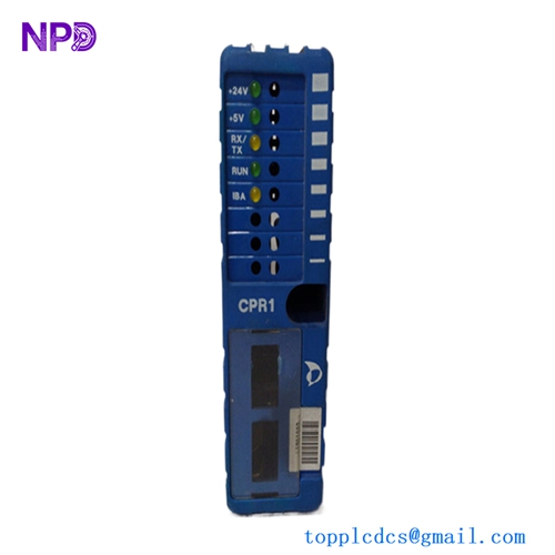
- Power On: Apply power and monitor the front-panel status LEDs.
- Signal Injection: Use a signal generator to simulate rotational pulses to verify the module registers accurate RPM values in the control software.
✅ Initial Operation Checklist
- Are all mounting screws and DIN rail clips secure?
- Is the network cabling shielded and routed away from high-voltage lines?
- Does the software display a “Heartbeat” or “Active” status for the module?
- Are the scaling parameters correctly mapped to the physical sensor output?
❓ Common Questions (Q&A)
Q: What does the flashing status LED indicate? A: A flashing LED typically indicates a communication loss or an invalid configuration parameter. Check your network wiring and IP settings. Q: Can this module be hot-swapped? A: It is recommended to power down the module before replacement to avoid potential surges, though the design supports rapid field replacement. Q: Is calibration required for this module? A: The module is factory-calibrated. However, field verification is recommended annually to ensure continued accuracy in harsh environments.