
Description
Product Introduction
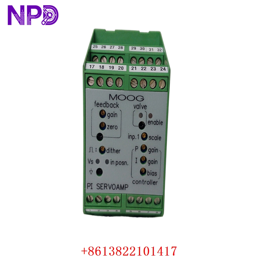
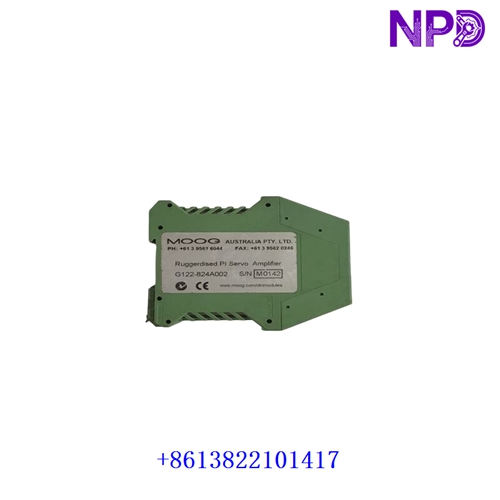
⚙️ Product: G122-824A002
🏷️ Brand: MOOG
🔧 Product Type: P-I Servoamplifier
💧 Application: Electro-Hydraulic Closed-Loop Control
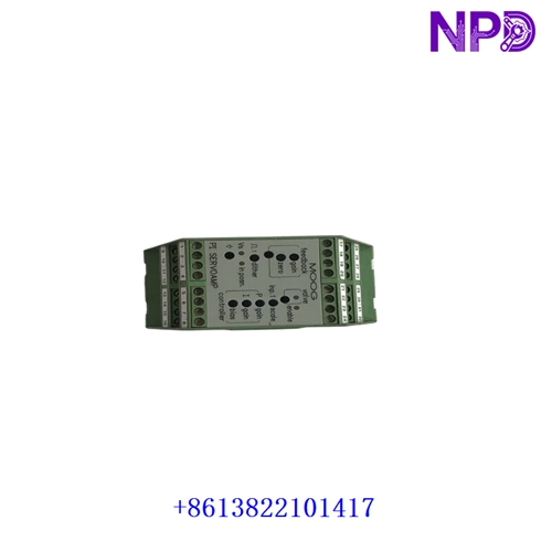
The MOOG G122-824A002 is an analog P-I servoamplifier designed for closed-loop industrial control applications. It accepts configurable analog command and feedback signals and produces a proportional control output for compatible servo or proportional valves. Available technical references identify the unit as a DIN-rail-mounted G122 series P-I servoamplifier.
🎛️ The amplifier provides selectable proportional, integral, or combined P-I control. Input and output ranges can be configured to suit different hydraulic control loops, making it useful for applications involving position, pressure, force, flow, or velocity control.
🔌 Before installation, verify the exact G122-824A002 configuration, internal switch settings, command input type, feedback signal, output range, servo valve compatibility, and 24 VDC supply.
Product Datasheet
🔹 Model: G122-824A002
🔹 Brand: MOOG
🔹 Product Type: Analog P-I Servoamplifier
🔹 Control Mode: Proportional / Integral / P-I, Switch Selectable
🔹 Input Signals: Two Single-Ended Inputs + One Differential Input
🔹 Input Range: 4–20 mA or ±10 V, Selectable
🔹 Feedback Input: Differential 4–20 mA or ±10 V, Selectable
🔹 Output Range: ±10 V, ±5 mA, ±10 mA, ±20 mA, ±30 mA, ±50 mA; maximum ±100 mA
🔹 Supply Voltage: 24 VDC nominal, 22–28 VDC
🔹 Current Consumption: 75 mA at 24 VDC no load; approx. 200 mA at 100 mA load
🔹 Mounting: DIN Rail
🔹 Protection: IP20
🔹 Operating Temperature: 0°C to +40°C
🔹 Dimensions: Approx. 100 × 108 × 45 mm
🔹 Weight: Approx. 180 g
🔹 Country of Origin: USA / configuration dependent
The core electrical and mechanical values above are reported in available G122-824A002 technical references.
Typical Applications
💧 Hydraulic servo control systems
⚙️ Electro-hydraulic actuators
🏭 Industrial machinery
🔩 Metal processing and rolling equipment
🛢️ Oil and gas control equipment
🧪 Test and simulation systems
⚡ Turbine and power-generation auxiliary control
Installation & Use
🛠️ Check the command and feedback signal ranges before wiring. Set the internal switches and potentiometers according to the approved control-loop design.
🔌 Supply the amplifier with a stable 24 VDC source and connect the command, feedback, enable, and servo-valve circuits according to the application wiring diagram.
🎛️ During commissioning, adjust zero, gain, and integral response gradually. Confirm that the feedback signal follows the actual actuator position or process variable.
📊 Test the system first at low command levels. Verify output polarity, feedback direction, valve response, stability, and fail-safe behavior before applying the full operating range.
⚠️ The G122-824A002 is an analog closed-loop controller; incorrect signal scaling or feedback polarity can cause unstable actuator behavior. Verify the complete hydraulic loop before putting the equipment into service.