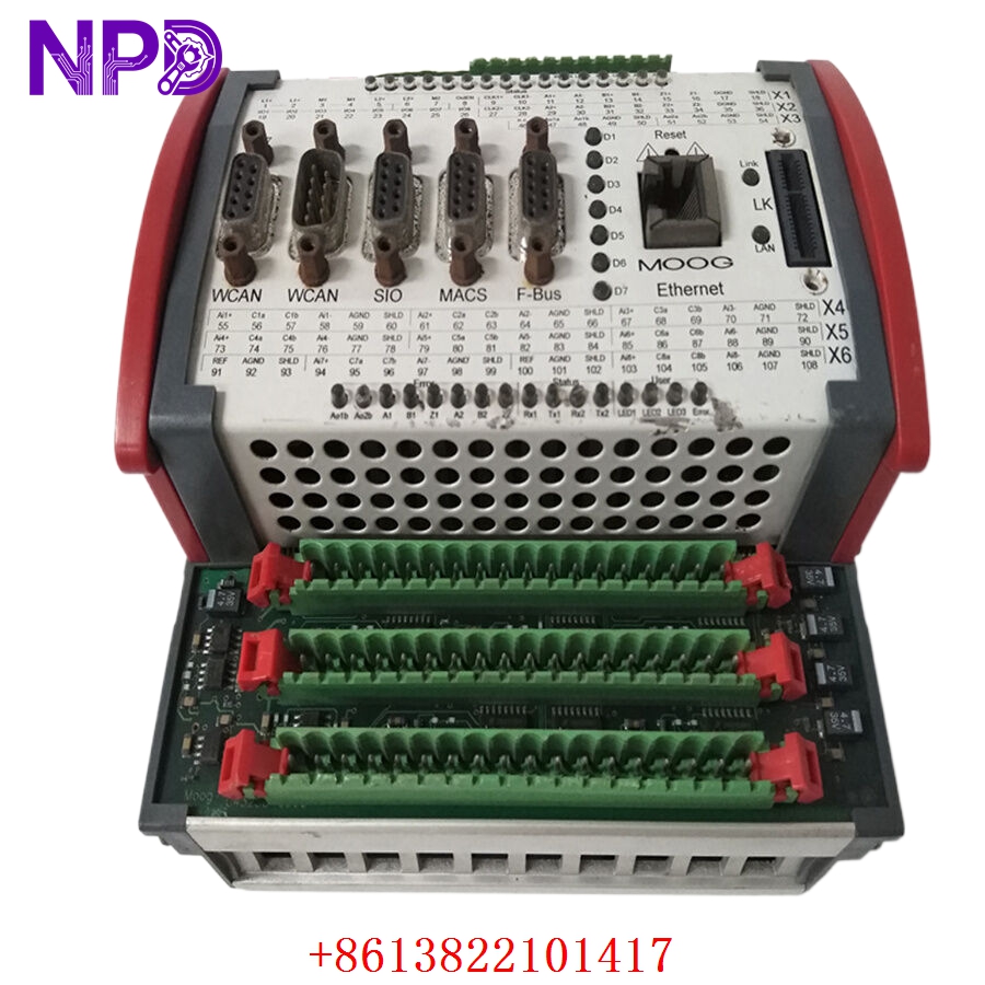
Description
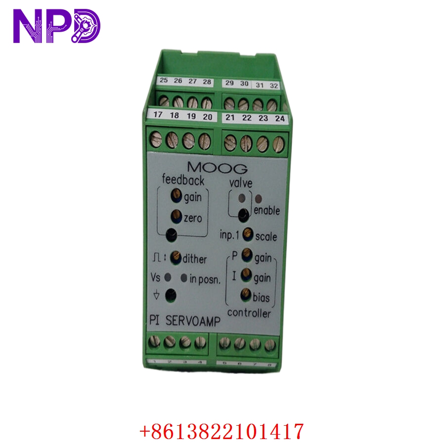
- Model: MOOG G122-824-002
- Brand: MOOG (USA/Germany)
- Series: G122 Series Servo Amplifiers
- Core Function: High-accuracy proportional-integral (P-I) control for servo valves
- Product Type: Servo Amplifier Module (DIN Rail Mount)
- Key Specs: 24 V DC Power ±10 V Input ±100 mA Output (Configurable)
- Supply Voltage: 24 V DC (18 to 35 V DC range)
- Input Signal: ±10 V standard (configurable via jumpers)
- Output Current: Max ±100 mA (adjustable for various valve coils)
- Control Characteristic: P (Proportional) or P-I (Proportional-Integral)
- Mounting: Symmetrical DIN rail (EN 50022)
- Front Panel Adjustments: Gain, Integrator Time, Deadband, Offset
- LED Indicators: Power, Signal Level, Fault Status
- Frequency Response: > 1 kHz (depending on settings)
- Enclosure Rating: IP20
- Dimensions: 100 x 22.5 x 113.5 mm (compact housing)
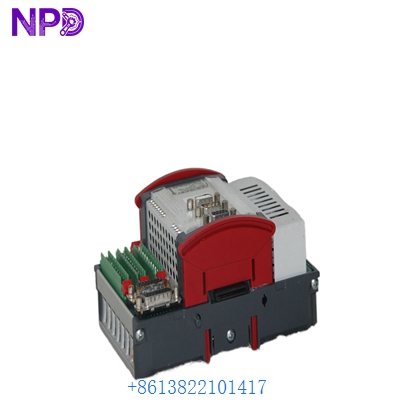
MOOG G122-824-002

MOOG G122-824-002
Application Scenarios & Pain Points
In high-precision hydraulic systems—like those used in plastic injection molding or aerospace test rigs—the interface between the controller (PLC) and the physical servo valve is critical. If your PLC sends a ±10 V command but the valve coil requires a specific current (like ±50 mA), the G122-824-002 acts as the essential bridge. The main pain point for engineers is “drift” or “sluggishness.” When an old amplifier starts to age, the integrator might not hold its zero point, leading to hydraulic cylinders “creeping” when they should be locked. Having a fresh, calibrated G122-824-002 is the only way to restore that crisp, sub-millimeter positioning accuracy.
Typical Application Scenarios:
- Plastic Injection Molding
Controlling the velocity and pressure phases (P/Q control) of the injection ram for consistent part quality.
- Steel & Aluminum Mills
Managing the gap control in rolling mills where high-frequency response is needed to maintain thickness tolerances.
- Flight Simulators & Test Rigs
Driving high-response valves for motion platforms where latency must be kept below 5 ms.
- Power Generation
Regulating steam turbine governor valves where stability and reliability are non-negotiable for grid synchronization.
Case Study: The “Creeping” Press in Ohio
Background:
A Tier-1 automotive supplier had a 500-ton hydraulic press that started failing quality checks. The ram was drifting by nearly 2 mm during the “hold” cycle.
The Problem:
The onsite team suspected the servo valve, but after swapping it, the problem persisted. They realized the old G122-824-002 amplifier in the cabinet was thermally sensitive; as the cabinet warmed up, the amplifier’s offset shifted. Moog’s lead time for a new unit was quoted at 10 weeks.
The Solution:
We shipped a new surplus G122-824-002 via overnight air. Before it left, we verified the current output range on our bench test to ensure it matched the factory ±100 mA default.
The Result:
The maintenance lead swapped the module, tuned the “Zero” and “Gain” pots on the front panel, and the press was back in production by the next afternoon. Total downtime was reduced from 2.5 months to less than 48 hours.
Compatible Replacement Models
可替代型号:
✅ 直接替换 (无需改动)
- MOOG G122-824-001
- 差异: -002 is the upgraded version of -001 with improved thermal stability. They share the same pinout and DIN rail footprint.
- 建议: 直接升级到 -002 即可。
⚠️ 硬件兼容 (需调整设置)
- MOOG G123-817
- 差异: This is a more complex controller (PID). It can drive the same valves but the setup software/potentiometers are different.
- 注意: Only use this if you need advanced features like dither control or ramping, otherwise stick to the G122.
❌ 不兼容
- MOOG Mop-Series Amplifiers
- 原因: These are older “Eurocard” format (3U height). They require a rack, not a DIN rail, and use completely different wiring connectors.
SOP Quality Transparency
For an analog servo amplifier, precision is everything. We treat these modules with “lab-grade” care.
- Visual & Source Audit:
We check the manufacturing date code and inspect the potentiometer seals. We ensure the DIN rail clips are robust and the terminal blocks show no signs of “screw-driver mash.”
- Bench Testing (Live Calibration):
We don’t just “lamp test” these. We use a Keithley 2400 SourceMeter to verify the following:
- Input Accuracy: We apply a precise 5.000 V command and measure if the output scales correctly based on the Gain setting.
- Integrator Check: We enable the “I” function and monitor the ramp-up time to ensure the internal capacitors haven’t dried out.
- Full Scale Output: We verify the module can hit the full ±100 mA (or your specific coil requirement) without clipping or oscillation.
- Noise Floor Test:
We use an oscilloscope to ensure the output signal is clean. A “noisy” amplifier leads to “jittery” valves, which eventually destroys the mechanical seals of the hydraulic cylinder.
- Packaging:
The module is placed in a silver-shielding ESD bag. We use custom-cut foam inserts to ensure the front-panel potentiometers aren’t bumped during transit.
Technical “Pitfall” Guide
Replacing a Moog amp isn’t just about the wires. In my experience, 80% of “bad” new modules are actually just misconfigured ones.
- The “Gain” Trap ❗
Every valve has a different “sweet spot.” If you install the new G122-824-002 and the system starts vibrating violently (hunting), your gain is too high.
The Fix: Before removing the old unit, count the number of turns from “fully counter-clockwise” on the Gain pot and replicate it on the new one. Or, start with low gain and slowly increase until the system is responsive but stable.
- Jumper Configurations (Internal) ❗
The G122 series has internal jumpers for input range (±10 V vs 4-20 mA) and P vs P-I mode.
The Fix: Open the housing! Slide the PCB out of the plastic shell (carefully) and compare the jumper positions with your old unit. If the old unit had the Integrator disabled (P-only) and the new one has it enabled (P-I), your system will likely overshoot.
- Nulling the Valve:
Hydraulic valves have a mechanical offset.
The Fix: With the command signal at 0 V, use the “Offset” (or Null) potentiometer on the front of the G122-824-002 to stop any cylinder movement. Don’t assume “0V in = 0mA out” is what the system needs.
- Power Supply Common:
In my experience, if you don’t tie the 0 V (Common) of your PLC output to the 0 V of the G122 power supply, you’ll get a “floating” signal that causes random erratic valve jumps. Check your grounds!
Troubleshooting Quick Reference
| Symptom | Possible Cause | Relevance | Quick Check | Recommendation |
| “PWR” LED Off | No 24V supply | ❌ Low | Measure terminals 1(+) and 2(-). | Check fuse/breaker. |
| System Oscillating | Gain too high | ✅ High | Turn the “Gain” pot CCW. | Reduce gain until stable. |
| Cylinder Creeping | Offset drift | ✅ High | Set command to 0V and check movement. | Adjust “Offset” pot until stop. |
| No Output Current | Input out of range | ⚠️ Med | Measure input voltage at terminals. | Check PLC AO card status. |
| Valve “Sticking” | Dither needed | ❌ Low | Check if the valve is old/dirty. | G122 doesn’t have dither; check valve mechanics. |
Need help with tuning? If you provide us with your valve model number (e.g., D661, D633), our engineers can pre-set the jumpers and gain pots for you before shipping. Just ask!