
Description
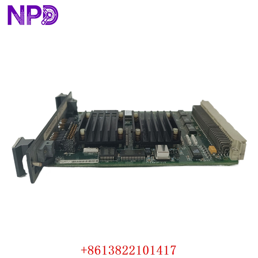
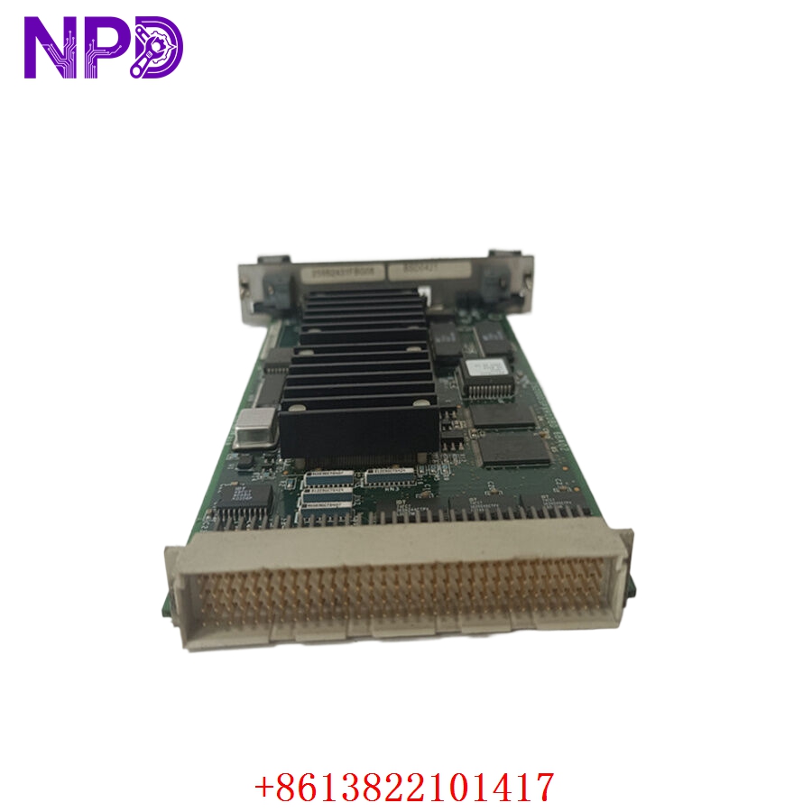
- Model: GE IS200DSPXH1DBD (Functional Acronym: DSPX)
- Brand: General Electric (USA)
- Series: EX2100 Excitation Control / Innovation Series Drives / Mark VI
- Core Function: Primary microprocessor processing engine for bridge regulation, motor control loops, and SCR gating sequences, New Surplus condition
- Type: Digital Signal Processor (DSP) Control Board
- Key Specs: 60 MHz processing clock, 5 V DC logic backplane input, onboard FPGA/ASIC custom arrays, 4 dedicated external interrupts
- Processor Core Architecture: High-speed Digital Signal Processor running at a native 60 MHz clock speed
- Internal Logic Coprocessor: Onboard custom ASIC / FPGA for deterministic gate pulse generation and hardware protection loops
- Power Supply Requirements: 5 V DC derived directly from the control rack backplane array
- Onboard Memory Subsystem: 1x FLASH block (boot images, app code), 1x SRAM array (execution variables), 1x NVRAM sector (non-volatile history logs)
- Revision Tracking: Integrated Add-Only electronic chip layer for hardware revision and serial tracking
- Interrupt Infrastructure: 4 discrete external hardware line interrupts (INT0 Stack Overflow, INT1 Inner Loop Load Pulse, INT2/INT3 Configurable)
- Backplane Interface: 32-bit data bus width via the primary P1 multi-pin connector rail
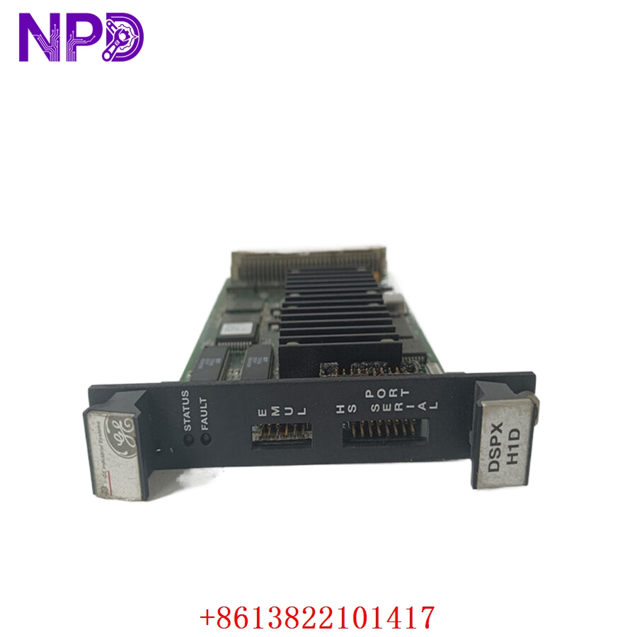
- Front Panel Tool Access: 1x P5 Texas Instruments emulator port (JTAG emulation & direct FLASH burning), 1x P6 TTL engineering monitor line
- Local Diagnostic Display: Dual LED arrangement (DS1 Red for system faults, DS2 Green for execution status mapping)
- Form Factor Standard: 3U Eurocard single-slot rack-mount dimensions (33.0 cm H x 17.8 cm W)
- Operating Temperature Limits: -30 °C to +65 °C
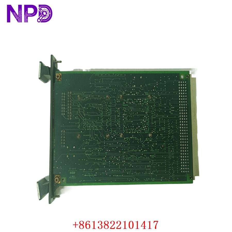
GE IS200DSPXH1DBD
GE IS200DSPXH1DBD
GE IS200DSPXH1DBD
Application Scenarios & Pain Points
When an industrial gas turbine or large synchronous drive infrastructure is running, the DSPX engine handles high-frequency outer loop conversions and SCR firing profiles. If this main processing card experiences an internal clock freeze or memory sector decay, your entire generator field excitation stops, causing a cascading plant shutdown. Tracking down an exact, verified replacement with the proper revision suffix is a massive bottleneck for maintenance managers. Installing an untested board or a mismatched revision variant can throw immediate backplane communication timeouts, extending critical turbine downtime for days while your operation loses massive revenue.
Typical Application Scenarios
- Power Generation – EX2100 Excitation Core
Manages automated Field Voltage Regulation (FVR) and Field Current Regulator (FCR) inner control loops, transferring SCR gate controls directly to the ESEL board.
- Heavy Industrial Plants – Innovation Series Motor Regulation
Executes advanced vector control, bridge firing sequences, and thermal dynamic estimation routines for massive industrial mill or compressor synchronous drives.
- Turbine Utilities – Generator Performance Simulation
Processes generator instrumentation feedbacks, executing high-speed localized over/under-excitation limiting and V/Hz threshold safety checks.
Real-World Field Case: Eliminating Intermittent Exciter Trips
Background: A steel fabrication mill in central China was utilizing an Innovation Series drive framework to manage their main structural rolling mills. The setup was tripping offline erratically once or twice a week.
The Problem: The local maintenance staff noticed the main controller rack would drop communication entirely, showing a generic “Inner Loop Timeout” warning inside Control System Toolbox. The red DS1 LED on the older DSPX board would strobe during the crash, but clearing the fault required a full cold reboot of the 5 V rack tier. The mill was losing hours of production scheduling to these random resets.
The Solution: Our depot team was contacted to source a direct replacement module. We pulled a clean revision variant from our warehouse, mounted it on our specialized test rack to run a continuous 24-hour thermal soak pass, verified the SRAM read/write integrity, and shipped the unit out via high-priority express freight.
The Result:
- Implementation: The on-site team swapped the malfunctioning processor card out during a planned 4-hour maintenance window, mirroring the exact software build version via the Control System Toolbox connection.
- Operational Outcome: The rolling mill resumed full production capacity immediately, with zero communication dropouts or loop synchronization timeouts recorded over the following operational quarters.
Compatible Replacement Models
Paying close attention to the revision designators on GE cards is vital to avoiding bus architecture mismatches during field installation.
- IS200DSPXH1D (Specifically the IS200DSPXH1DBD lot) → Direct Drop-in Replacement
- Differences: This represents the mature, updated Revision D hardware configuration. It features improved board thermal footprints and updated surface-mount component traces.
- Action: Slide directly into the single 3U rack slot. No physical loom changes required.
- IS200DSPXH1A / IS200DSPXH1B → Software Compatibility Check Needed
- Differences: These are early-generation board layouts. While they perform the identical baseline core tasks, their bootloader versions and memory allocations differ.
- Action: When swapping an older ‘A’ or ‘B’ layout for a ‘D’ revision, you must verify that your system application files and your baseline Toolbox software version support the updated board ID profile.
Troubleshooting Quick Reference
Keep this diagnostic matrix handy when troubleshooting a suspect DSPX module on the control floor.
| Bezel Indication | Probable Failure Source | Hardware Relevancy | Field Validation Test | Resolution Protocol |
| DS1 (Red) Solid ON; DS2 (Green) Solid OFF | Total board lockup or core processing failure | ✅ High | Attempt to establish a tool connection via the P6 engineering terminal line. Check for system responses. | The board is locked in a permanent reset or watchdog loop. Replace the DSPX module immediately. |
| DS2 (Green) Solid ON (Not flashing) | Execution code execution halted or stopped | ⚠️ Medium | Check your Control System Toolbox software interface to view the current master execution state. | Re-load the application code blocks using the Unit Data Highway or via the designated tool port to restart the processing stack. |
| DS1 (Red) Flashing; DS2 (Green) Flashing | Internal hardware interrupt fault triggered | ✅ High | Query the Diagnostic Buffer inside the toolbox software. Look up active memory error tags. | Indicates an internal stack overflow (INT0) or memory parity issue. Clear the buffer; if it recurs immediately, replace the card. |
| Both LEDs remain dark after powering the frame | Complete loss of 5 V logic backplane feed | ❌ Low | Pull the board slightly and test the main power rail inputs across the backplane slots using a digital multimeter. | The issue lies with the source power supply board or the rack power distribution loops, not the processing board itself. |
❗ CRITICAL VERSION COMPLIANCE WARNING: When installing a replacement processor board, you must read and record the existing DIP jumper traces and configuration settings from your old board. Never boot a new DSPX module without matching these hardware parameters to your site’s specific application schematics, or you risk executing incorrect gating sequences on your active SCR bridge.
If your plant engineering crew needs to verify our current inventory’s exact firmware compatibility profiles or requires a detailed walkthrough of our automated validation processes before placing a shipment block, connect with our support desk today. We will deliver the data you need within two hours.