Description
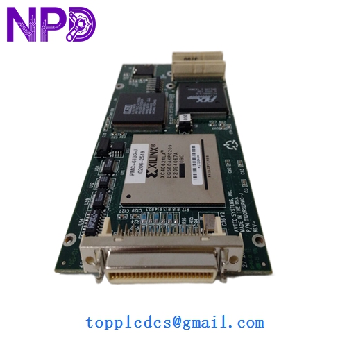
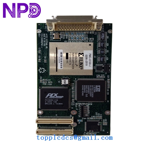
- Model: PMC-6130-J
- Part Number: 0100RSDPMC-J
- Brand: Motorola (Embedded Computing)
- Architecture: PowerPC (typically MPC74xx series)
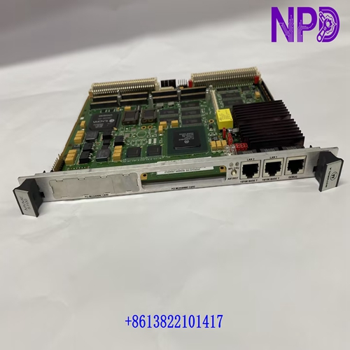
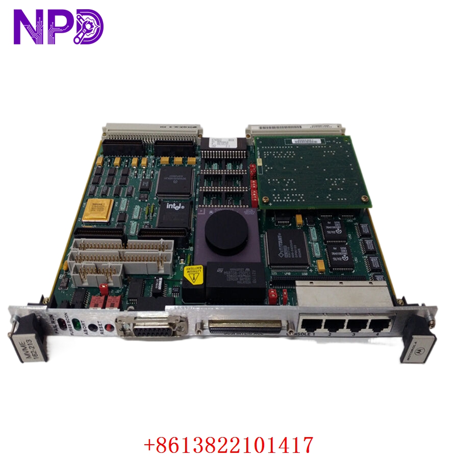
- Function: Processor Mezzanine Card (PMC) for VME Carrier Boards
- Form Factor: IEEE 1386.1 PMC Standard
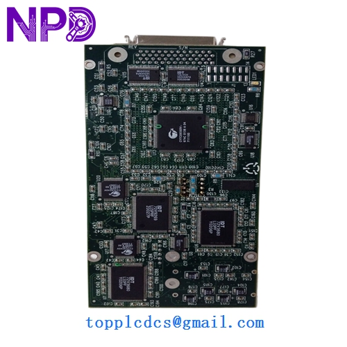
- CPU: High-performance PowerPC processor (speed varies by sub-revision, typically 400MHz – 500MHz range).
- Memory: Onboard SDRAM (typically 64MB to 256MB) and Flash memory for OS storage.
- Bus Interface: 32/64-bit PCI interface at 33/66 MHz, compliant with PMC standards.
- I/O Connectivity: Standard front-panel or rear-panel I/O options (P14 mapping) depending on the carrier board configuration.
- Operating System Support: Highly optimized for real-time operating systems (RTOS) including VxWorks, LynxOS, and QNX.
- Power Consumption: Low-power design suitable for conduction-cooled or fan-cooled VME racks.
MOTOROLA PMC-6130-J 0100RSDPMC-J
MOTOROLA PMC-6130-J 0100RSDPMC-J
MOTOROLA PMC-6130-J 0100RSDPMC-J
MOTOROLA PMC-6130-J 0100RSDPMC-J
Installation & Configuration Guide
Phase 1: Pre-Installation (Preparation: 15 minutes)
⚠️ Critical Warning: The PMC-6130-J is a high-density electronic component. Improper seating on the carrier board can lead to a short circuit that may destroy both the PMC and the expensive VME host board.
- Carrier Compatibility: Verify that your VME carrier board (e.g., MVME5100, MVME5500) has an open PMC slot and supports the 0100RSDPMC-J revision.
- Jumper Verification: Check the carrier board jumpers for PCI signaling voltage (3.3V vs. 5V). The PMC-6130-J must match the carrier’s signaling voltage.
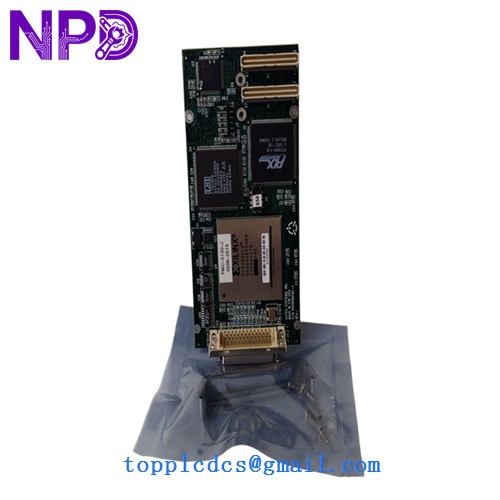
- ESD Safety: Use a grounded anti-static mat and wrist strap. Mezzanine cards are extremely sensitive to static discharge.
Phase 2: Mounting & Seating (Step-by-Step)
- Align Connectors: Align the PMC connectors (P1, P2, P3, P4) with the mating connectors on the VME carrier board.
- Pressure Application: Apply firm, even pressure to the center of the PMC card until you feel the connectors click into place. Do not rock the card back and forth.
- Secure Screws: Use the provided mounting screws to secure the PMC to the carrier board standoffs. This ensures mechanical stability under vibration and provides a ground path.
Phase 3: Commissioning
- Insert VME Board: Slide the combined VME/PMC assembly into the rack and lock the injector/ejector handles.
- Boot Monitoring: Connect a terminal to the VME board’s console port.
- Hardware Verification: During the boot sequence (e.g., MOTLoad or PPCBug), verify that the system detects the PMC mezzanine and correctly identifies the processor and memory.
Customer Cases & Industry Applications
Case 1: Defense Radar System Maintenance A military radar installation utilized VME racks for signal processing. A failure on the mezzanine CPU caused the radar to lose tracking resolution. Because Motorola had long since discontinued the PMC-6130-J, the facility faced a massive cost for a total system redesign. We provided a New Surplus 0100RSDPMC-J, allowing for a simple card-swap that restored full capability for a fraction of the upgrade cost.
Case 2: Industrial Imaging Upgrade A high-speed industrial inspection line required additional processing power to handle new high-resolution cameras. By adding a PMC-6130-J to their existing MVME carrier boards, the plant doubled their local processing throughput without having to rewire their control cabinets or change their VME backplane architecture.
Frequently Asked Questions (FAQ)
Q: Can I use the PMC-6130-J on a non-Motorola carrier board? A: Yes, as long as the carrier board follows the IEEE 1386.1 PMC standard and the operating system has the appropriate drivers for the PowerPC architecture.
Q: Does it come with the operating system pre-installed? A: No. Mezzanine cards are typically “blank” or contain only a basic bootloader. You must load your specific RTOS (VxWorks, etc.) via the carrier board’s network or serial interface.
Q: Why choose “New Surplus” over “Refurbished”? A: PMC cards use high-density connectors that have a limited number of “mating cycles.” Refurbished cards may have worn or slightly bent pins that cause intermittent data errors. New Surplus ensures pristine connectors and 100% factory reliability for mission-critical apps.
Q: What is the “J” suffix in the part number? A: The “J” typically denotes a specific revision or environmental rating (such as an extended temperature range or a specific hardware build version). Always match the 0100RSDPMC-J part number exactly for critical replacements.