
Description
🌐 Product Overview
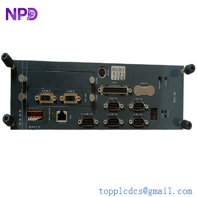
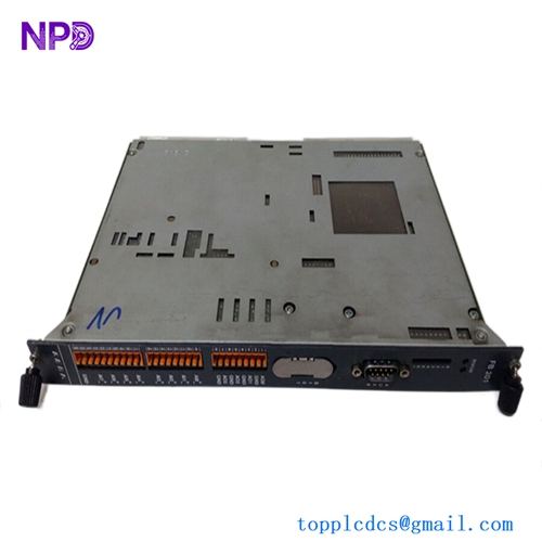
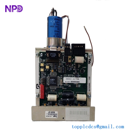
The Norcontrol NA-1E221.3 is a marine-certified, high-reliability control panel interface board designed for integration within Norcontrol (Kongsberg Maritime) automation frameworks, such as the legacy DataChief and AutoChief propulsion and monitoring systems. Operating as a critical localized processing module, this PCB acts as the bridge between operator panel tactile switches, numerical indicators, and the central system controller. Engineered to withstand the constant vibration, thermal fluctuations, and saline environments typical of shipboard control consoles, the NA-1E221.3 ensures uninterrupted operator input and reliable field telemetry translation.

⚙️ Technical Specifications
- Series: DataChief / AutoChief Control Component Line
- Dimensions: 210mm x 155mm x 25mm
- Weight: 0.52 kg
- Origin: Norway
- Logic Architecture: Integrated industrial microprocessor with localized bus transceivers
- Power Demand: 24V DC nominal (18V to 32V DC wide operational maritime tolerance)
- Input Interfacing: Matrix scanning circuitry for physical tactile keys, emergency stops, and switches
- Output Capabilities: Multi-channel drivers for LED indicators, background illumination, and local audible buzzers
🚀 Application Fields
- Propulsion Control Consoles: Managing bridge or Engine Control Room (ECR) throttle commands and main engine start/stop/emergency panels.
- Machinery Monitoring Systems: Interfacing operator control inputs with alarm management panels across auxiliary systems.
- Cargo Operations: Integration within mimic panels for liquid cargo ballast control, valve actuation, and tank level monitoring.
- Generator Distribution Boards: Power system panel operator interfaces for synchronizing and monitoring marine diesel generators.
📖 Product Instructions
- Panel Installation: Isolate the control console from all active power grids. Mount the NA-1E221.3 card securely into its panel alignment brackets behind the console faceplate using non-conductive standoffs and lock washers to resist physical shocks.
- Ribbon and Harness Hookup: Plug the operator panel keyboard membrane or tactile matrix ribbon cable into the dedicated onboard headers, ensuring the locking clips snap into place. Connect the system data bus and power distribution lines to the primary screw-terminal or multi-pin block.
- Grounding Compliance: Secure a dedicated low-impedance ground wire from the PCB’s grounding terminal pad directly to the underlying copper chassis ground bar to ensure optimal signal integrity and electrostatic dissipation.
✅ Initial Startup Checklist
- Verify that the primary 24V DC feed matches nominal voltage and correct polarity before applying power.
- Confirm that all external wire connectors, edge connectors, and ribbon harnesses are pushed completely flat and locked in place.
- Power up the station and confirm that the onboard green “HEALTHY” or “RUN” diagnostic LED begins to flash, indicating stable firmware initialization.
- Perform a local panel lamp test through the system control configuration to verify that all integrated LED indicators and backlights illuminate uniformly.
🛠️ Maintenance & Care
- Fastener and Connector Tightness: Inspect the mounting bolts and wire terminal screws every six months to correct any loosening caused by continuous hull and mechanical vibrations.
- Debris & Salt-Crust Removal: Periodically spray the board surfaces with high-purity electronic contact cleaner and wipe with a soft, anti-static brush to remove conductive dust, salt spray residue, or oil film buildup.
- Component Tracking: Inspect the board annually for physical degradation, focusing on potential heat discoloration around onboard voltage regulators or any bulging of electrolytic filtering capacitors.
⚠️ Safety Precautions
- Static Charge Safeguards: Always wear a grounded electrostatic discharge (ESD) wrist strap when handling the board to prevent permanent latent damage to the sensitive CMOS logic gates.
- Isolate Grid Power: Never remove, replace, or re-wire the panel card while the main power supply or upstream battery backup arrays are active.
- Cable Separation Rules: Route low-voltage panel signal and communication lines completely clear of high-voltage breaker charging motors or AC motor starter cables inside the console ducting.
🔍 Troubleshooting & FAQ
- Q: The operator panel keys are entirely non-responsive, but the board’s power LED is glowing.
- A: This points to a broken interface matrix connection or a data link break with the host processor. Check the continuity of the ribbon cable running from the keys to the NA-1E221.3 board, and verify that the module address matches the system map.
- Q: Certain status LEDs flicker erratically on the panel face plate.
- A: This behavior is typical of loose terminal pins or poor localized grounding. Re-torque the output terminal blocks and inspect the main console earth bonding strap for rust, corrosion, or high resistance.
- Q: Can this panel card be swapped out while the host system remains fully operational?
- A: Hot-swapping parameters vary by generation. While the underlying data bus may support live replacement, it is strongly advised to power down the specific console rack during a port stay to prevent transient bus errors from halting active monitoring processes.