
Description
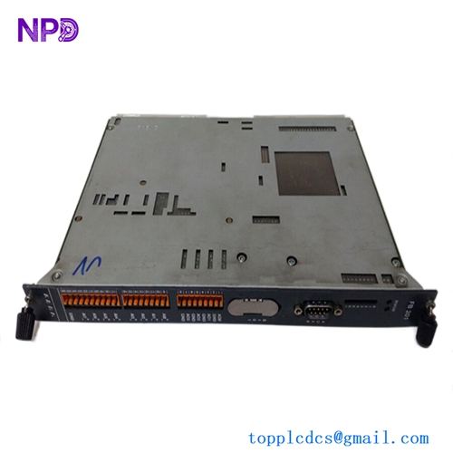
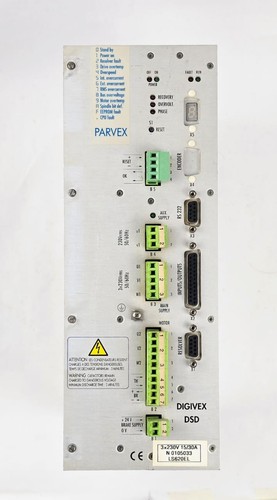
The Parvex DSD13015 (SSD Drives / Parker Hannifin) is a high-performance digital servo drive from the Digivex DSD product line. Engineered for the precise torque, speed, and positioning control of brushless AC synchronous servo motors, the DSD13015 features advanced microprocessor-driven field-oriented control loop algorithms. This compact, panel-mounted drive is designed for high-dynamic motion applications, providing industrial machinery with exceptional acceleration characteristics, smooth low-speed torque delivery, and seamless integration into automated fieldbus networks.
⚙️ Technical Specifications
- Series: Digivex DSD Digital Servo Drive Line
- Model Code: DSD13015
- Dimensions: 265mm x 75mm x 195mm
- Weight: 2.80 kg
- Origin: France / Germany
- Nominal Current: 15A RMS (Continuous output capacity)
- Peak Output Current: 30A RMS (Available during high-torque acceleration phases)
- Main Supply Input: 3-Phase 230V AC / 400V AC nominal operational window
- Auxiliary Control Power: 24V DC (Maintains logic and diagnostics when main AC power is isolated)
- Feedback Compatibility: Resolver interface, high-resolution incremental encoders, or single/multi-turn absolute encoders
🚀 Application Fields
- CNC Machine Tools: High-precision feed axis control for automated milling, routing, and turning centers.
- Packaging Machinery: Coordinating high-speed indexing, filling, cutting, and wrapping operations.
- Robotics and Material Handling: Powering joint actuators in multi-axis robotic arms and precise pick-and-place gantry configurations.
- Textile and Printing Production: Managing precise web-tension controls and synchronized multi-axis electronic line-shaft systems.
📖 Product Instructions
- Panel Installation: Mount the DSD13015 servo drive vertically inside a well-ventilated, IP54-rated industrial control enclosure. Ensure a minimum clearance of 40mm at the top and bottom of the unit to permit unrestricted cooling airflow across the integrated aluminum heatsink fins.
- Power & Motor Connections: Wire the 3-phase AC mains supply to the designated input terminal block. Connect the servo motor’s power lines to the UVW output terminals using a low-impedance, shielded cable. Ensure the cable shield is clamped securely to the drive’s chassis ground plane.
- Feedback Interface: Plug the pre-fabricated resolver or encoder cable into the corresponding high-density DB-style signal socket on the front face of the drive. Keep this low-voltage signal routing physically separated from the high-voltage motor power conductors.
✅ Initial Startup Checklist
- Verify that the mains voltage profile aligns with the exact configuration configuration window mapped on the drive’s side identification placard.
- Confirm that all external brake resistor connections are properly fused and wired to the dedicated regenerative energy dissipation circuit.
- Apply the 24V DC auxiliary logic power; verify that the front panel status character display lights up and does not immediately lock onto a hardware error code.
- Execute an initial software tuning or autostop routine via a connected programming terminal to calibrate the drive’s current loop matrices to the attached servo motor’s electrical constants.
🛠️ Maintenance & Care
- Heatsink Debris Clearing: Inspect the integrated cooling fan and exhaust vents bi-annually. Clear out internal dust accumulations using dry, low-pressure compressed air to prevent thermal derating conditions.
- Connection Re-Torque Audits: Check the tight clamp torque parameters of the primary power terminal screws every six months to correct any loose terminations caused by persistent machinery harmonic vibrations.
- Bus Capacitor Monitoring: Review the DC bus stabilization metrics through your diagnostics software utility annually to trace any early indicators of internal electrolytic capacitor degradation.
⚠️ Safety Precautions
- High Voltage Residual Charge: Wait at least 10 minutes after disconnecting all primary AC power inputs before touching any internal terminal connections. The internal DC bus capacitors retain dangerous high-voltage electrical potentials (>500V DC) that require time to bleed off through internal discharge circuits.
- Strict Power Off Compliance: Never isolate or plug in the motor power terminal block (U, V, W) while the drive is actively energized, as the resulting high-voltage inductive arcing will permanently destroy the output IGBT inverter modules.
- Low-Impedance Earthing: The drive must be bonded to a central, heavy-duty copper ground bus via a low-impedance connection to prevent high-frequency electromagnetic noise interference and minimize electrical shock risks to personnel.
🔍 Troubleshooting & FAQ
- Q: The front panel alpha-numeric display flashes an “OU” or “Overvoltage” trip code when the motor decelerates.
- A: This indicates that the regenerative energy generated by the motor during braking has driven the internal DC bus voltage above safe limits. Check the continuity and resistance values of the external braking resistor, and ensure the internal braking chopper transistor configuration is active.
- Q: The drive triggers an “OC” or “Overcurrent” fault immediately upon initiating a movement command.
- A: This points to an immediate electrical short circuit. Disconnect the motor cable from the drive and test the lines for phase-to-phase or phase-to-ground shorts using an insulation resistance meter. If the cable checks out cleanly, the drive’s internal inverter power stage may be damaged.
- Q: Can the DSD13015 run standard 3-phase asynchronous induction motors in open-loop mode?
- A: No. The Digivex DSD series is explicitly designed as a closed-loop servo controller for synchronous permanent-magnet brushless motors. Attempting to run standard induction motors without compatible rotor position feedback will result in an immediate motor synchronization or commutation fault.