
Description
🌐 Product Overview
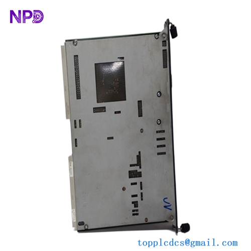
The Samsung SSAS-Master S RSPC-X32 is a highly reliable, marine-certified redundant system process controller designed for integrated automation systems (IAS) and shipboard machinery control. Engineered to deliver continuous execution of critical process logic, the RSPC-X32 features dual-processor redundancy that ensures bumpless switchover in the event of a hardware or communication failure. It serves as the core processing engine within complex marine networks, managing large-scale data aggregation, alarm monitoring, and propulsion system coordination without risking operational downtime.

⚙️ Technical Specifications
- Series: SSAS-Master S Automation Series
- Dimensions: 260mm x 145mm x 180mm
- Weight: 4.20 kg
- Origin: South Korea
- Processor Architecture: 32-Bit High-Speed Industrial RISC Processor
- Redundancy Interface: Dedicated ultra-fast hardware synchronization link
- Communication Interfaces: Redundant Ethernet (100Base-TX), Isolated RS-485/422, and CAN bus rails
- Operating Voltage: Dual 24V DC inputs (with integrated power management and isolation)
🚀 Application Fields
- Integrated Automation Systems (IAS): Centralized control of machinery spaces, bilge networks, and ballast pumping systems on commercial vessels.
- Propulsion Control Loops: Real-time Governor and Controllable Pitch Propeller (CPP) system oversight demanding absolute system uptime.
- Cargo Handling Systems: Automated valve control, tank level gauging, and vapor recovery management on LNG and chemical tankers.
- Power Management Interfacing: Redundant coordination link operating alongside heavy-duty marine switchboards and generator controllers.
📖 Product Instructions
- Rack Installation: Mount the controller module onto the specialized SSAS-Master S heavy-duty chassis sub-rack. Ensure the module is fully pushed back into the backplane socket and tighten the front retaining screws to resist maritime hull vibrations.
- Redundancy Link Pairing: Connect the dedicated high-speed optical or copper synchronization cable between the Master (Primary) and Slave (Backup) RSPC-X32 units to establish the mirror memory data pipeline.
- Network Topology: Connect the primary and secondary network cables to the isolated LAN ports to build out a ring topology, preventing communication losses from a singular cable break.
✅ Initial Startup Checklist
- Verify that both primary and backup auxiliary power supply links are delivering clean, unfused 24V DC to the chassis backplane.
- Confirm that the redundancy synchronization cable is securely locked into both the A and B controllers.
- Apply power and watch the front panel diagnostic status cluster; the “SYS” light should go steady green and the primary controller should indicate “ACTIVE” while the secondary indicates “STANDBY”.
- Initiate a system heartbeat check via the workstation console to ensure the tag database is actively synchronizing between both processors.
🛠️ Maintenance & Care
- Switchover Testing: Conduct a manual redundancy switchover test every six months during scheduled port stays to verify that the standby controller takes over the process smoothly without dropping active outputs.
- Airflow Audits: Clean out the chassis ventilation slits annually with non-conductive pressurized air to maintain optimal processor temperature.
- Diagnostic Log Verification: Periodically pull the internal error log buffer from the controller memory to check for transient memory allocation faults or network packet retries.
⚠️ Safety Precautions
- Bumpless Isolation: Never pull or hot-swap the active “Primary” controller while modification updates or flashing tasks are actively processing on the standby unit.
- Chassis Grounding: Ensure the controller chassis frame is securely tied to the vessel’s common earth copper strip to mitigate common-mode noise issues.
- Electrostatic Discharge: Maintain a grounded interface when interacting with the bare ports of the module to shield the 32-bit internal registers from static breakdown.
🔍 Troubleshooting & FAQ
- Q: The front panel indicates a “SYNC FAIL” alarm LED code. What is the breakdown?
- A: This indicates that the primary and secondary controllers are running independently and cannot sync memory. Check for a damaged or loose redundancy pairing cable, or verify that both controllers are running identical firmware revisions.
- Q: The controller unexpected switches roles from Primary to Standby without an explicit command.
- A: The internal self-supervision circuit triggers an automatic switchover if it catches a localized hardware fault, a power drop on one of the 24V rails, or a major task cycle timeout. Check the system log for specific error trap codes.
- Q: How do I reload the baseline runtime logic if the internal memory becomes corrupted?
- A: Connect a configuration workstation via the front serial service port or over the LAN line, boot the controller into diagnostic programming mode, and perform a full cold download of the validated project backup.