
Description
🌐 Product Overview
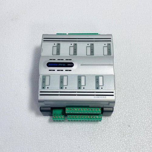
The Samsung SSAS-PRO SPAO-8 is an industrial-grade, 8-channel analog input and alarm monitoring module designed specifically for marine vessel management and centralized machinery supervision systems. Operating as a critical data acquisition node within the Samsung SSAS-PRO architecture, this module continuously monitors high-precision field sensors such as temperature detectors (RTDs, thermocouples), pressure transmitters, and level sensors. It provides real-time threshold validation, localized alarm processing, and seamless network telemetry to safeguard vital marine engines, auxiliary machinery, and cargo systems.
⚙️ Technical Specifications
- Series: SSAS-PRO Marine Automation Component Line
- Dimensions: 175mm x 120mm x 65mm
- Weight: 0.85 kg
- Origin: South Korea
- Input Capacity: 8 Independent Analog Channels (Configurable for 4-20mA, 0-10V, or PT100 inputs)
- A/D Conversion Resolution: 16-bit high-precision delta-sigma converters
- Supply Voltage: 24V DC nominal (18V to 32V DC operational range)
- Isolation Protection: 1500V AC optical isolation between field inputs, logic circuit, and communication network
🚀 Application Fields
- Machinery Space Monitoring: Real-time temperature tracking for main engine bearings, exhaust gas systems, and cooling water loops.
- Tank Level Gauging: Processing analog hydrostatic or radar sensor data from fuel oil, ballast water, and bilge tanks.
- Cargo Supervision: Tracking pressure and temperature fluctuations inside cargo holds on specialized gas and chemical carriers.
- Auxiliary System Automation: Monitoring hydraulic power packs, air compressor discharge pressures, and lubrication oil manifolds.
📖 Product Instructions
- Module Mounting: Secure the SPAO-8 module onto a standard TS35 DIN rail inside a protective, vibration-damped marine control enclosure. Connect the module ground terminal directly to the cabinet enclosure earth bar.
- Field Instrument Wiring: Route analog sensor cables through shielded twisted pairs. Connect inputs to the designated channels on the pluggable terminal blocks, ensuring that cable shields are grounded at the cabinet entry point only.
- Network Setup: Adjust the hardware address rotary switches on the module housing to assign a unique node ID within the SSAS-PRO network segment, then attach the communication bus cable.
✅ Initial Startup Checklist
- Verify that the auxiliary 24V DC power feed matches the voltage and polarity specifications printed on the module case.
- Confirm that the input type configuration jumpers (or software settings) match the physical sensor type attached to each of the 8 channels.
- Power up the unit and confirm that the green “RUN” or “SYS” status LED blinks rhythmically, indicating normal firmware execution.
- Check the workstation display terminal to ensure all 8 analog loops report valid data profiles without highlighting open-circuit or short-circuit sensor faults.
🛠️ Maintenance & Care
- Terminal Screw Audits: Inspect and re-torque the pluggable terminal block screws every six months to counteract loosening caused by continuous hull and engine vibrations.
- Surface Dust Mitigation: Clean the external module casing using a dry, anti-static microfiber cloth during routine machinery space maintenance to prevent salt or dust bridging.
- Calibration Verification: Verify channel measurement accuracy annually using an external loop calibrator to ensure internal analog-to-digital circuits have not drifted beyond specified class tolerances.
⚠️ Safety Precautions
- Isolate Electrical Sources: Disconnect the primary 24V DC power supply and isolate field loops before removing the module or modifying terminal connections.
- Shielding Rules: Always maintain proper cable shield continuity to prevent electromagnetic interference from heavy shipboard machinery from corrupting low-level analog signals.
- Static Discharge Defense: Keep the module inside its static-shielding pouch until installation, and handle it exclusively by the plastic enclosure to avoid static damage to sensitive conversion chips.
🔍 Troubleshooting & FAQ
- Q: A specific channel reports a maximum scale value (e.g., 22mA or 10.5V) and triggers an “Overrange” alarm.
- A: This typical behavior indicates an open circuit or a broken wire in the field loop. Inspect the external sensor wiring, check the terminal connections, and measure the loop current using a digital multimeter.
- Q: The module fails to communicate with the central processing unit, and the “COMM” LED remains unlit.
- A: Check that the module’s node address rotary switch matches the address mapped in the system configuration software. Also, verify network bus cable continuity and ensure the 120-ohm bus termination resistors are correctly placed at the ends of the network link.
- Q: Can different types of sensors (e.g., a 4-20mA sensor and a PT100 RTD) be mixed across the 8 channels simultaneously?
- A: Yes, the SPAO-8 supports independent channel configuration. Each channel can be mapped individually via the system software programming interface to match the designated field instrument characteristics.