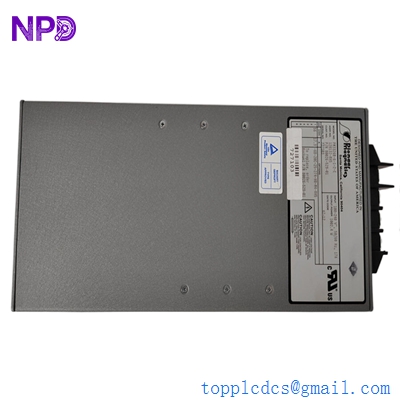
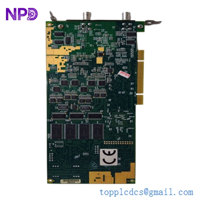
Description
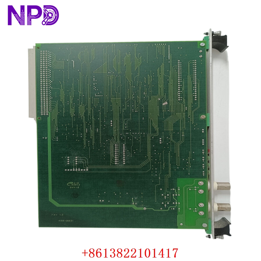
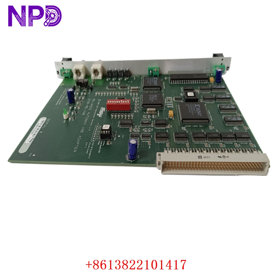
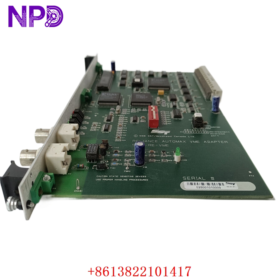
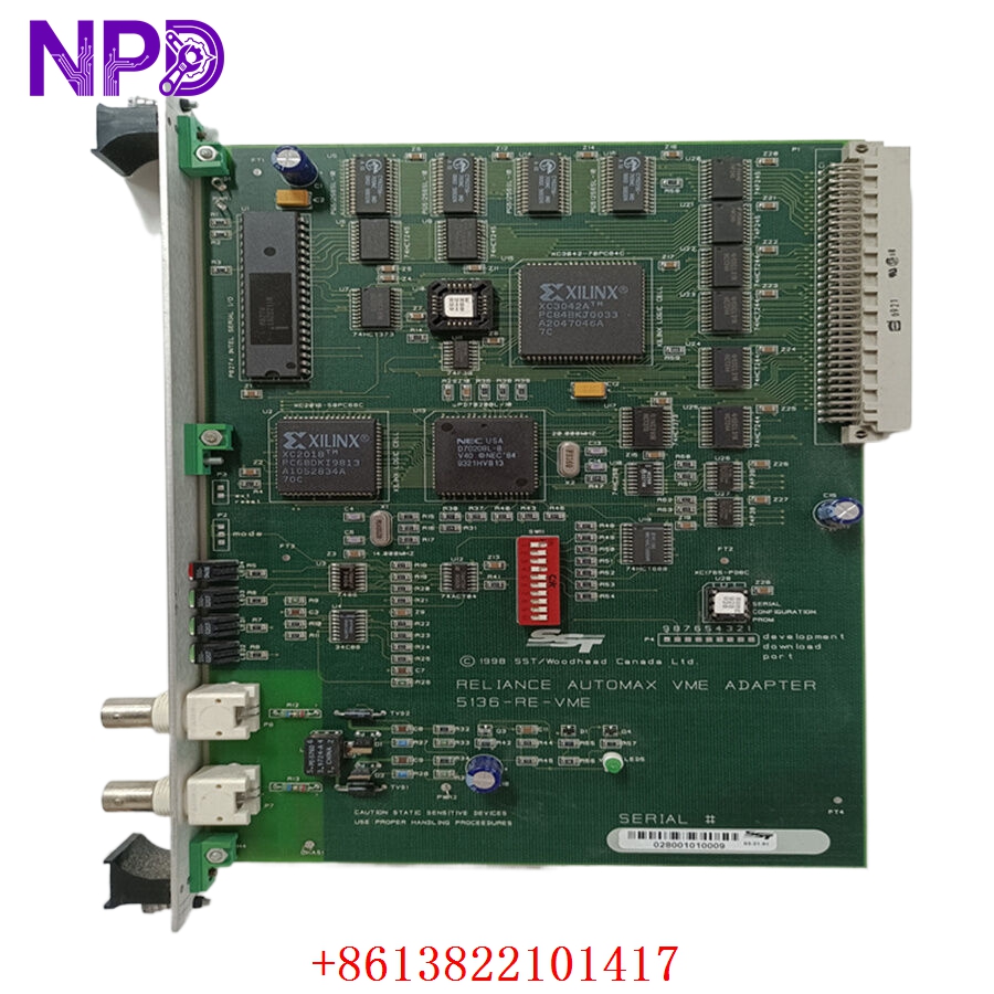
- 🔢 Model: 5136-RE-VME
- 🏢 Brand: SST (Molex)
- ⛓️ Series: VMEbus Communication Series
- 💡 Core Function: High-performance Profibus interface for VMEbus-based industrial systems
- 🛠️ Type: Communication Module (VME)
- ⚡ Key Specs: VMEbus backplane connectivity, Profibus DP master/slave support
- 🖥️ Bus Interface: VMEbus (Standard 6U format)
- 📡 Profibus Protocol: Profibus DP Master/Slave
- ⏱️ Data Throughput: High-speed cyclic data transfer
- 🔋 Power Consumption: +5 V DC (Backplane supplied)
- 🌡️ Operating Temp: 0°C to 60°C
- 🔩 Connector: 9-pin D-sub (Profibus)
- 🛡️ Protection Rating: IP20
- 🛠️ Configuration: Compatible with SST Profibus Configuration Software
- 💡 Status Indicators: Status, Error, and Network activity LEDs
Installation & Configuration Guide
Phase 1: Preparation (20 mins)
⚠️ Safety First:
- Power down the entire VME chassis before handling modules.
- 🧤 Use a grounding strap; the VMEbus backplane and module circuitry are highly sensitive to ESD.
- Ensure the Profibus network is idle to prevent communication errors during startup.
Phase 2: Installation (25 mins)
- 📸 Record Settings: Before removing an existing card, document the physical slot number and the jumper/switch configurations (if any) on the module.
- 🔩 Detachment: Unscrew the front panel fasteners. Use the extraction levers to gently unlock and pull the module from the chassis.
- 📥 Insertion: Align the 5136-RE-VME with the card guides. Push firmly until the backplane connectors engage fully. Tighten the front panel screws.
- 🔌 Wiring: Attach the Profibus cable. Ensure the shield is properly terminated to avoid electromagnetic interference.
Phase 3: Testing & Commissioning (15 mins)
- 🟢 Power-Up: Apply power to the VME chassis. The status LED should indicate a successful internal power-on self-test (POST).
- 💻 Software Integration: Connect via the VME system bus. Use the SST configuration tool to download the GSD files required for your specific Profibus network.
- 🔄 Network Scan: Initiate a network scan to identify slave devices.
- 📊 Validation: Monitor the diagnostic LEDs—solid green indicates operational status, while blinking indicates a configuration or network fault.
Customer Cases & Industry Applications
Case: Legacy VMEbus Test Stand Upgrade
- Situation: A major aerospace testing lab utilized a VME-based test stand. The existing 5136-RE-VME communication card failed due to a sudden power spike.
- Task: The entire test sequence for a new actuator could not proceed without Profibus connectivity to the PLC.
- Action: They reached out to our surplus department. We provided a unit that had been tested for bus-to-Profibus throughput and verified for legacy VME chassis compatibility.
- Result: Installation was seamless. Because the module was an identical match to the legacy hardware, the test team avoided re-programming the VME controller and met their delivery deadline. The lab subsequently purchased a second unit to store on-site for immediate disaster recovery.
Frequently Asked Questions (FAQ)
Q: Can I use this card in any VME chassis? A: The 5136-RE-VME is a standard VMEbus 6U module. Provided your chassis supplies the required voltage and has an available VME-compliant slot, it should be fully compatible.
Q: Is the firmware on this module compatible with older VME systems? A: Yes, these modules are typically backward compatible. However, if you are running an extremely old version of the configuration software, you may need the corresponding legacy driver files. We can assist in sourcing these if needed.
Q: Why does the module have a 9-pin D-sub connector? A: This is the industry-standard interface for Profibus DP connections. Ensure you are using a high-quality, shielded Profibus cable to prevent signal attenuation over long runs.
Q: What if the module isn’t detected by the VME CPU? A: Check that the module is fully seated in the backplane. Verify that the bus address settings (if configured via jumpers) match the memory map defined in your system software. If the LED remains dark, check your VME power supply rail for +5 V.