Description
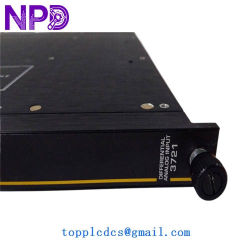
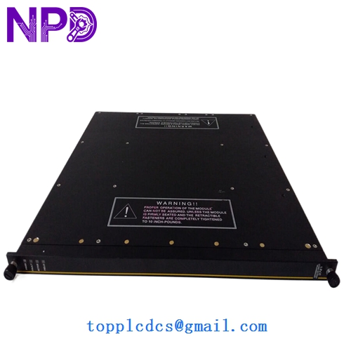
- Model: 3721
- Brand: Triconex (by Schneider Electric)
- Series: Tricon v9/v10 Triple Modular Redundancy (TMR) System
- Core Function: High-reliability Analog Input for safety-critical applications
- Condition: New Surplus (Original, non-refurbished, guaranteed genuine)
- Type: Analog Input Module (AI)
- Key Specs: 32 Channels | 0-5 VDC Range | TMR Architecture
- Input Channels: 32 Differential, Isolated points
- Input Signal Range: 0 to 5 VDC
- Architecture: Triple Modular Redundant (TMR) with three independent paths
- Input Impedance: > 10 MΩ
- Resolution: 12-bit
- Scan Rate: 50 ms (nominal)
- Accuracy: < 0.15% of FSR (Full Scale Range) from 0 to 60°C
- Isolation: 1,000 VDC (Input-to-Field, Input-to-Chassis)
- Power Consumption: < 10 Watts
- Compliance: SIL 3 (Safety Integrity Level) Rated
- External Termination: Requires specific External Termination Panels (ETP)
Installation & Configuration Guide
Phase 1: Pre-Installation (10 Minutes)
⚠️ Safety Protocol:
- This is a SIL 3 rated safety system. Ensure all bypasses are active and local safety protocols are signed off before interacting with the rack.
- Confirm the version of the Tricon chassis and the TriStation 1131 software build.
- Verify that the current system is in a “Healthy” state via the diagnostic LEDs on the MP (Main Processor).
Backup & Documentation:
- Open TriStation 1131 and verify the I/O configuration for Slot # where the 3721 is located.
- Take a clear photo of the existing External Termination Panel (ETP) wiring.
Phase 2: Removal of Faulty Module (5 Minutes)
- Since the Tricon is a TMR system, the 3721 supports Hot-Swap capability. You do not need to power down the rack.
- If the module is “Active,” ensure the “Active” LED is off on the faulty unit (the redundant partner should take over).
- Loosen the top and bottom retaining screws.
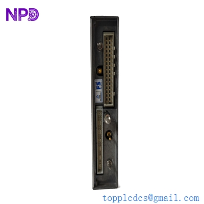
- Firmly pull the module handles outward to disengage the backplane connector. Slide the module out smoothly.
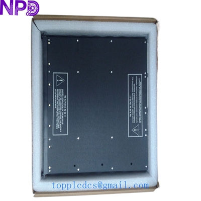
TRICONEX 3721
Phase 3: Installing the New 3721 (15 Minutes)
- Visual Inspection: Check the 96-pin backplane connector for any bent pins. Ensure the “New Surplus” unit has no dust in the connectors.
- Keying: Verify that the keying on the slot matches the module to prevent accidental insertion of a different module type.
- Insertion: Slide the module into the guide rails. Push firmly until the module is flush with the rack.
- Locking: Tighten the retaining screws to ensure continuous grounding and vibration resistance.
Phase 4: Commissioning & Validation (15 Minutes)
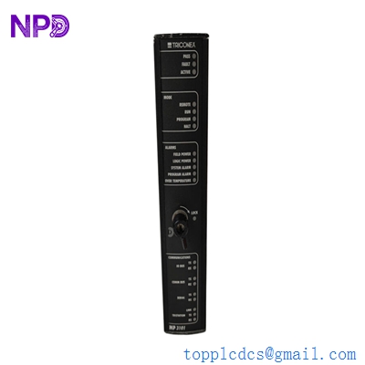
- LED Check:
- PASS: Should light up green after internal self-tests (approx. 10-20 seconds).
- ACTIVE: Should light up once the Main Processor recognizes and assigns it to the control loop.
- FAULT: Should remain OFF. If red, check TriStation diagnostics for specific error codes.
- Software Validation: – Monitor the “Module Information” in TriStation.
- Verify that the 32 input channels are reporting values within the expected range (typically 1-5V for 4-20mA loops across a 250Ω resistor).
- Loop Check: Simulate a signal at the ETP for at least one critical loop to confirm the end-to-end integrity of the new module.
Customer Cases & Industry Applications
Case 1: Offshore Platform ESD System Recovery A major operator in the North Sea faced a “Module Fault” on a Triconex 3721 responsible for fire and gas detection. Due to the TMR architecture, the system stayed online, but the safety integrity was “degraded” (running in 2-out-of-3 mode transitioned to 1-out-of-2). Local vendors quoted a 14-week lead time. We provided a tested New Surplus unit from our Singapore hub within 72 hours. The platform avoided a mandatory safety shutdown that would have cost over $500,000 per day in deferred production.
Case 2: Nuclear Power Plant Maintenance Cycle During a planned refueling outage, a nuclear facility in East Asia identified three 3721 modules with aging electrolytic capacitors during bench testing. Rather than opting for risky “third-party repairs” which often void safety certifications, they chose our New Surplus inventory. By replacing the aging units with original, unused stock, they extended the lifecycle of the v9.6 system by another 10 years without the massive capital expense of a full v11 system migration.
Frequently Asked Questions (FAQ)
Q: Does the 3721 support 4-20 mA signals? A: Directly, the 3721 is a 0-5 VDC module. To use it with 4-20 mA field devices, you must use an External Termination Panel (ETP) with 250 Ω precision resistors. This converts the 4-20 mA signal to the 1-5 VDC range the module expects.
Q: What is the difference between 3721 and 3700? A: In my experience, the 3721 is the high-density version (32 channels) designed for newer Tricon racks, whereas the 3700 is an older, lower-density model. The 3721 offers significantly better isolation and diagnostic capabilities for modern SIL 3 requirements.
Q: Can I hot-swap this module while the process is running? A: Yes. Triconex is designed for this. When you pull one 3721, the other two legs in the TMR architecture continue to vote and maintain the output. However, I always tell my clients: Check your “Fault” lights on the other legs first. You don’t want to pull a module if the redundant partners aren’t healthy.
Q: Is “New Surplus” as reliable as “Factory New”? A: For a module like the 3721, yes. These units are often kept as “Insurance Spares” by large plants and never installed. We perform a rigorous “Live Test” on a Tricon v10 rack (using Fluke 754 calibrators) to ensure the 12-bit ADC is perfectly calibrated. You get factory performance at a secondary market price point.
Q: How do I handle a “Load/Dump” error after installation? A: This usually means the firmware on the new 3721 is different from the existing modules in the rack. You may need to use TriStation to perform a “Firmware Update” to match the system version. If you are unsure, provide us with your system version at the time of purchase, and we will attempt to match the firmware before shipping.