
Description
Product Overview
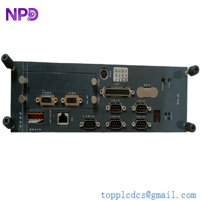
The Tyco OCM800 (part number 125-585-615) is a high-reliability operator control printed circuit board (PCB) designed for industrial fire alarm control panels and marine safety monitoring systems. It acts as the primary interface bridge between the main system processor and the operator panel display and control inputs. Engineered for continuous operation in demanding environments, this board ensures reliable tactile feedback, status indication, and stable communication under critical safety conditions.
Technical Specifications
- Part Number: 125-585-615
- Device Type: Operator Control Panel PCB Module
- Dimensions: Approximately 210 mm x 145 mm x 25 mm
- Weight: 0.38 kg
- Original Origin: United Kingdom
- Operating Voltage: 24 VDC (nominal)
- Interface Types: Ribbon cable connection to display, bus communication to host CPU
Application Areas
🔥 Commercial Fire Alarm Control Panels 🚢 Marine Vessel Safety and Monitoring Systems 🏭 Industrial Facility Gas and Hazard Detection Units 🏢 Building Automation Safety Networks 🔒 Critical Infrastructure Control Rooms

Operational Guidelines
Power-Up / Power-Down Sequence
- Startup: Ensure the main control panel housing is fully powered off before installation. Securely seat the OCM800 module onto its mounting standoffs and connect the system bus ribbon cables. Turn on the main panel power supply. The onboard status LEDs should flash during initialization and then remain solid, indicating successful handshake with the main CPU.
- Shutdown: Before removing or servicing the PCB, completely isolate and power down the main fire panel or control cabinet. Wait at least 30 seconds for all onboard capacitors to discharge completely before disconnecting any interface or ribbon cables to prevent electrostatic damage.
Step-by-Step Standard Operation
- Visual Audit: Regularly check the module for dust accumulation or signs of thermal stress on components.
- Interface Connection: Verify that all data bus ribbons and power wires are firmly locked into their respective terminal sockets.
- Keyboard Testing: Use the system diagnostic menu on the control panel to perform a lamp and button test, ensuring the OCM800 accurately registers user input.
- Signal Verification: Monitor the communication LEDs on the board to confirm stable tx/rx data flow with the motherboard.
Frequently Asked Questions
Q: What causes the control panel to report a “Card Missing” or communication fault for the OCM800? A: This usually points to a loose or damaged data ribbon cable running from the PCB to the central processor. Inspect the cable pins for alignment and ensure the connectors are clicked firmly into place.
Q: Can this board be swapped out while the system is live? A: No. Hot-swapping the OCM800 is highly discouraged and can cause electrical shorts or firmware corruption on the main processor card. Always power down the entire panel before replacing components.
Q: Are individual buttons or LEDs on the board repairable in the field? A: Component-level soldering on the board is not recommended as it may void system certifications. Defective units should be replaced as a whole module to maintain fire safety compliance.
Q: How can I protect the OCM800 from static damage during maintenance? A: Always wear a properly grounded ESD (Electrostatic Discharge) wrist strap when touching or working near the component side of the printed circuit board.