
Description
📝 Product Overview
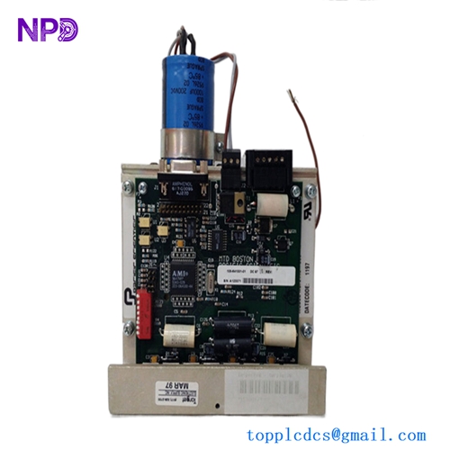
The Tyco PS-136 (Part Number 509.023.051) is a high-performance, marine-approved power supply module optimized for addressable fire alarm control systems and industrial safety signaling networks. Engineered to deliver clean, regulated DC voltage under volatile input conditions, this modular unit features integrated battery charging management and comprehensive fault-monitoring circuits to guarantee uninterrupted operation of critical life-safety infrastructure.

⚙️ Technical Specifications
- 📐 Dimensions: 185 mm x 110 mm x 65 mm
- ⚖️ Weight: 1.15 kg
- 🌍 Country of Origin: United Kingdom
🚢 Applications
- Tyco Minerva marine and land-based fire alarm panels
- Integrated safety instrumented systems (SIS)
- Dedicated backup battery charging arrays
- Auxiliary low-voltage power distribution networks
🛠️ Usage Instructions
- Confirm that the input voltage selection jumper is correctly set to match your local utility grid before applying power.
- Ensure backup batteries are connected with correct polarity to avoid blowing the integrated DC protection fuses.
- Test the automatic power-fail transfer mechanism periodically by isolating the primary AC grid input during scheduled maintenance checks.
- Keep the status LEDs clearly visible through the cabinet window to track normal, battery-only, or fault conditions.
🔧 Mechanical Installation Requirements
- Fixing Method: Standard DIN-rail clip-on assembly or direct surface mounting onto backplates inside the control enclosure using four M4 screw standoffs.
- Space Clearance: Leave a minimum boundary clearance of 40 mm on all sides to prevent heat trap zones.
- Heat Dissipation: Arrange the module vertically within the lower section of the enclosure, ensuring that hot air can escape upward away from sensitive microprocessor cards.
🔌 Electrical Wiring Guide
- Terminal Definitions: * Terminals L, N, PE: Primary AC supply lines (Live, Neutral, Protective Earth)
- Terminals +BAT, -BAT: Standby lead-acid battery connection loop
- Terminals +DC, -DC: Regulated system output distribution ports
- Terminals NC, COM, NO: Volt-free fault signaling relay contacts
- Wire Gauge: Implement minimum 1.5 mm² (16 AWG) solid or stranded copper wire for the mains AC feed and 2.5 mm² (14 AWG) for the battery and core DC links.
- Grounding Norms: Connect the PE terminal to the chassis star ground point with a dedicated low-impedance ground wire to shield the internal switching components from transient surges.
📡 Communication Configuration
- IP Address: Not applicable. This component operates as a hardware-level power converter and doesn’t host an Ethernet layer.
- Station ID: Hardwired monitoring node; links to the main controller’s supervision loop via dedicated dry-contact error registers.
- Baud Rate: Not applicable. Fault status indicators transfer instantly via discrete binary voltage states rather than serial protocol networks.
❓ Frequently Asked Questions (Q&A)
- Q: Why is the yellow “Battery Fault” LED illuminated on the module?
- A: This indicates either the backup batteries are disconnected, the cell voltage has fallen below the minimum threshold, or the internal battery fuse is open.
- Q: Does the PS-136 automatically restart after a complete power failure?
- A: Yes, once primary AC utility power returns, the module instantly restores its main DC output and automatically begins recharging the standby battery banks.
- Q: Can I use this power supply to directly drive heavy inductive loads like magnetic door holders?
- A: Yes, provided the total continuous current draw remains within the module’s rated parameters and flyback diodes are installed at the load to catch inductive voltage spikes.