
Description
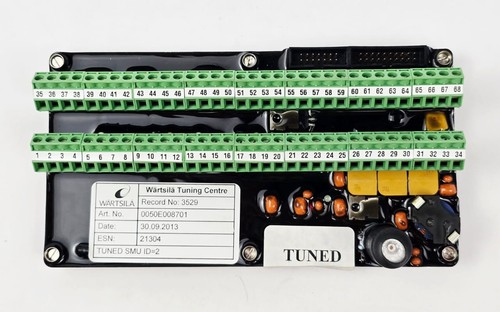
The Wartsila 0050E008701 is a high-performance, marine-certified Sensor Monitoring Unit (SMU) board engineered for integration within Wartsila’s advanced engine control and monitoring architectures, such as the UNIC and WECS automation systems. Operating as a heavy-duty data acquisition and signal processing card, this board interfaces directly with an array of critical engine sensors. It consolidates raw analog parameters (such as exhaust gas temperatures, oil pressures, and vibration profiles) into filtered, high-speed digital data streams for the main engine control computers, enabling precise thermal management and real-time fault diagnostics.
⚙️ Technical Specifications
- Part/Model Number: 0050E008701 (SMU Architecture)
- Dimensions: 233mm x 160mm x 24mm (Standard Eurocard Form Factor)
- Weight: 0.55 kg
- Origin: Switzerland / European Union
- Input Compatibility: Multi-channel interface supporting PT100/PT1000 RTDs, Thermocouples, and 4-20mA current loops
- Power Demand: 24V DC nominal (Supplied directly from the system rack backplane or localized power buses)
- Data Telemetry: High-speed, redundant CAN bus interfaces and RS-485 serial communication loops
- Isolation Rating: Galvanic isolation up to 1500V AC to protect core logic circuitry from field-side electrical surges
🚀 Application Fields
- Exhaust Gas Monitoring: Real-time multi-cylinder temperature tracking on large-bore Wartsila 2-stroke and 4-stroke marine diesel or dual-fuel engines.
- Bearing Temperature Tracking: Continuous monitoring of main bearings, crankpin bearings, and crosshead temperature sensors to prevent catastrophic engine seizures.
- Condition-Based Maintenance (CBM): Aggregating vibration, crankcase pressure, and liner temperature variables for preventative maintenance log analytics.
- Power Plant Automation: Distributed sensor data collection for land-based stationary Wartsila power generation plants.
📖 Product Instructions
- Card Installation: Power down the central sub-rack or monitoring enclosure completely. Align the 0050E008701 card with the guide rails of the designated slot. Push the board firmly inward until the multi-pin backplane connectors seat completely, then tighten the front panel retention fasteners.
- Field Sensor Wiring: Terminate sensor transmission shielding loops properly at the cabinet grounding bar. Ensure low-voltage sensor lines run through dedicated shielded twisted-pair cables isolated from high-voltage alternator or heavy starter motor leads.
- Node Mapping: Configure the physical node ID or slot assignment via the onboard DIP switch matrix (if applicable) or map the configuration profile using the proprietary Wartsila engine software tool to synchronize the card with the centralized control network.
✅ Initial Startup Checklist
- Verify that the sub-rack power distribution module is turned off before inserting or extracting the board hardware.
- Confirm that all input configurations (jumpers or software selections) match the exact type of physical sensor wired to each input channel.
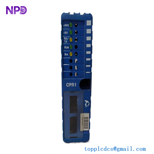
- Power up the automation panel and observe the front-facing diagnostic cluster; the green “RUN” or “OK” LED must light steady without triggering amber or red error lights.
- Log into the main Engine Control Room (ECR) workstation to verify that the corresponding sensor values populate the mimic display cleanly without flagging open-circuit or out-of-bounds loop faults.
🛠️ Maintenance & Care
- Backplane Pin Inspections: Periodically remove the card during scheduled vessel dry-dock overhauls to inspect the gold-plated rear pins for signs of salt-crust accumulation, oil film, or surface tarnishing. Clean safely with specialized high-purity contact cleaner.
- Hardware Tightness Audits: Re-verify the torque of the front panel retention screws every six months to counteract loosening caused by continuous hull and mechanical machinery vibrations.
- Calibration Compliance Verification: Check loop measurement drift annually using an external precision process simulator to ensure the onboard analog-to-digital converters remain within classification society tolerances.
⚠️ Safety Precautions
- Avoid Live Component Extraction: Never pull, plug, or reconfigure jumpers on the SMU board while the rack backplane is energized to avoid triggering high-frequency data bus corruption or destructive hardware shorts.
- Electrostatic Charge Safeguards: Always handle the board by its front panel edges or use a grounded ESD wrist strap to protect the high-density surface-mount microprocessors from catastrophic static puncture.
- Maintain Shielding Integrity: Never bypass or break sensor cable shielding loops, as electromagnetic cross-talk from high-amperage propulsion machinery will corrupt low-level sensor telemetry data.
🔍 Troubleshooting & FAQ
- Q: A grouping of channels suddenly displays a maximum scale read-out and triggers an “Open Circuit” alarm.
- A: This indicates a physical break in the field wire loop or a detached connector block. Check the external cable integrity up to the junction box, measure loop resistances using a multimeter, and ensure the input connector plug is fully seated on the board.
- Q: The board power LED is completely dark, but neighboring cards in the sub-rack operate normally.
- A: Inspect the onboard surface-mount protection fuses situated close to the backplane power input traces. A blown fuse typically indicates a voltage spike on a field sensor line or a dead short circuit within the external wiring harness.
- Q: Is a unique firmware upload necessary when installing a replacement 0050E008701 board?
- A: The core firmware profile is uniform across this series of Sensor Monitoring Units. The board reads its precise execution mapping and channel address definitions directly from the master controller configuration or physical address DIP switches. Ensure that the replacement board matches the physical hardware revision index of the original unit.