
Description
The Wartsila Sam Electronics AEM 402 is a high-density, marine-certified analog input module designed for integration within Sam Electronics’ proprietary automation platforms, including the NACOS (Navigation and Command System) and MCS (Machinery Control System) series. Operating as a data conversion engine, this module interfaces with multiple high-precision field sensors across a vessel’s machinery spaces. The AEM 402 converts raw analog telemetry—such as current loops, voltages, and resistance profiles—into filtered, synchronized digital data streams, allowing the central automation network to execute precise process loops and monitoring tasks.

⚙️ Technical Specifications
- Series: Sam Electronics Monitoring & Control Component Line
- Dimensions: 172mm x 114mm x 45mm
- Weight: 0.68 kg
- Origin: Germany
- Input Channels: Multi-channel configuration supporting 4–20mA, 0–10V DC, and standard RTD (PT100) sensor inputs
- Resolution: 16-bit analog-to-digital (A/D) conversion precision
- Operating Power: 24V DC nominal (18V to 32V DC maritime operating range)
- Isolation Rating: 1500V RMS galvanic isolation protecting core internal circuitry from field spikes
🚀 Application Fields
- Propulsion Systems Performance: Real-time processing of pressure and temperature inputs from fuel oil, lube oil, and cooling water systems.
- Integrated Navigation Systems (NACOS): Interfacing with meteorological sensors, wind direction indicators, and gyrocompass auxiliary metrics.
- Tank Level Management: Processing analog signals from hydrostatic, pneumatic, or radar transmitters mounted in fuel, ballast, and cargo tanks.
- HVAC and Auxiliary Supervision: Monitoring ambient engine room temperatures, cargo hold ventilation pressures, and exhaust line drafts.
📖 Product Instructions
- DIN Rail Mounting: Snap the AEM 402 module onto a standard TS35 DIN rail inside a vibration-damped cabinet layout. Connect the integrated grounding clip to an unpainted, clean section of the grounded rail frame.
- Field Instrument Wiring: Route analog sensor cables through twisted-pair shielded wires. Terminate the wire strands firmly into the screw-clamped pluggable blocks, keeping sensor routing separate from high-current AC motor cabling.
- Address Hardware Selection: Align the physical rotary hex dials or internal jumpers to configure the unique hardware communication index required by the primary network controller map.
✅ Initial Startup Checklist
- Verify that the primary 24V DC bus distribution matches voltage limitations and polarity indicators on the module frame.
- Confirm that the channel configuration jumpers or dip-switches are set accurately to match the connected sensor type (e.g., current loop vs. RTD).
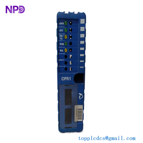
- Apply power and watch the diagnostic indicators; the green “PWR” light must shine steady and the “RUN” indicator should blink dynamically.
- Monitor the primary workstation mimic panel to ensure all analog points register values within normal operating metrics without displaying configuration timeout codes.
🛠️ Maintenance & Care
- Terminal Screws Retightening: Inspect the pluggable connection blocks every six months to correct any loosening caused by continuous hull or structural vibration patterns.
- Surface Dust Clearing: Keep the external module plastic casing free from salt spray tracks, oil film, or airborne dust particles using a dry, anti-static micro-fiber cloth.
- Calibration Compliance Verification: Perform loop accuracy tests annually using an external process simulator to verify that the internal 16-bit A/D conversion circuit remains within classification society tolerances.
⚠️ Safety Precautions
- Electrical Isolation Protocols: Disconnect the primary auxiliary power line and completely isolate field current loops before attempting to unseat or replace the AEM 402 hardware assembly.
- Electrostatic Charge Defenses: Always utilize a grounded ESD wrist strap when handling the card to shield the internal surface-mount components from catastrophic static puncture.
- Maintain Shielding Integrity: Never omit or bridge input cable shields; improper grounding of analog shields will allow heavy machinery electromagnetic fields to distort data variables.
🔍 Troubleshooting & FAQ
- Q: A specific channel locks onto a maximum reading (such as 22.8mA) and displays a “Wire Break” fault code.
- A: This usually indicates an open-circuit fault in the external field loop. Inspect the external sensor wire trace for physical breaks, verify that the transmitter has sufficient loop voltage, and ensure the pluggable module block is pinned tightly.
- Q: The communication “COM” LED flickers red and the main screen reports a packet collision error.
- A: This behavior points to conflicting station ID addresses or an un-terminated data line. Verify that the hardware address dial does not duplicate another module index on the network branch, and ensure that the end-of-line termination resistors are in place.
- Q: Can the input types be modified dynamically via system software without handling physical jumpers?
- A: The AEM 402 utilizes physical onboard layout configuration parameters to establish the electrical path for the designated input signal type. Always ensure the physical jumpers match the software tag mapping definitions to avoid data distortion or component overheating.