
Description
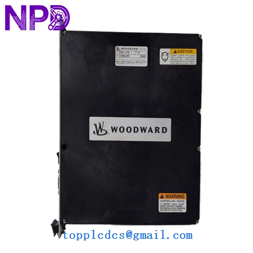
- Model Designation: WOODWARD 5417-174
- Module Type: Discrete Input/Output (I/O)
- System Platform: MicroNet Simplex / MicroNet TMR
- Discrete Inputs: 48 Channels (24 VDC Nominal)
- Input Filter: 1 ms hardware filter
- Logic Voltage: +5 VDC (Backplane Sourced)
- Isolation: 500 Vrms to Chassis; 500 Vrms to Control Logic
- Operating Temperature: -40°C to +70°C (-40°F to +158°F)
- Mounting: MicroNet 7-slot or 14-slot Chassis
- Compliance: CE, UL/cUL Listed, Class I Div 2
The Woodward 5417-174 is a high-density discrete input module designed for the MicroNet control platform, specifically built to handle large-scale digital signal acquisition in turbine and engine governing systems. It provides 48 independent channels for monitoring field contacts, limit switches, and status alarms. With its rugged design and millisecond-level response time, this module ensures high-speed data throughput and reliable signal integrity for mission-critical industrial automation applications.
Distinctions from Similar Models
- Channel Density: The 5417-174 offers 48 discrete inputs, doubling the capacity of standard 24-channel modules (such as the 5466 series) within a single rack slot.
- Input Filtering: Features an optimized hardware-based debounce filter (1 ms) that is specifically tuned for high-speed turbine trip logic, providing faster processing than legacy general-purpose I/O cards.
- TMR Efficiency: While compatible with Simplex systems, its architecture is optimized for Triple Modular Redundant (TMR) configurations, allowing for high-density voting without exhausting rack space.
Product Operation Guidelines
- Chassis Grounding: Ensure the MicroNet chassis is grounded to a single point to prevent electrical noise from causing “ghost” signals on the 48 high-density input channels.
- Terminal Matching: Always use the designated Field Terminal Modules (FTMs) and mass-termination cables provided by Woodward to ensure correct pin mapping and signal isolation.
- Inrush Management: When connecting long field wire runs, account for the 2.5 mA per channel draw to ensure the 24 VDC field power supply is adequately sized for all active inputs.
- Diagnostic LEDs: Monitor the module’s status LEDs during power-up; a steady green “OK” LED indicates the internal logic is synchronized with the CPU, while a red LED indicates a backplane communication fault.