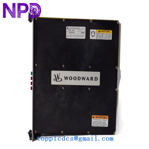
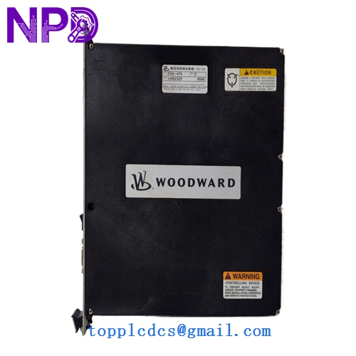
Description
- Model: 5501-470
- Brand: Woodward (USA)
- Series: MicroNet TMR / MicroNet Plus Control Systems
- Core Function: High-precision RTD (Resistance Temperature Detector) Input Module
- Condition: New Surplus (Original factory stock, verified non-refurbished)
- Type: Temperature Monitoring / Control Module
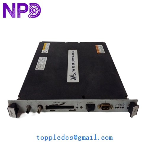
- Key Specs: 8-Channel RTD | 100-ohm Platinum (Pt100) | MicroNet Backplane Compatible
- Input Channels: 8 Differential RTD Inputs
- RTD Types: Supports 100-ohm Platinum (standard), 200-ohm, or 500-ohm (config dependent)
- A/D Resolution: 16-bit High Resolution
- Accuracy: Within 0.1% of full scale at 25°C
- Scan Rate: 5 ms per channel (nominal)
- Isolation: 500 Vrms to backplane / 0 V to field (common mode limits apply)
- Operating Temp: -40°C to +70°C (Industrial Grade)
- Power Input: Provided via MicroNet power supply backplane
- Communication: High-speed VME-based backplane architecture
- Certification: CE, UL/cUL Listed, Class I Div 2 (Hazardous Locations)
Installation & Configuration Guide
Phase 1: Pre-Installation (10 Minutes)
⚠️ Safety Protocol:
- Notify the control room that temperature loops (Bearing temp, Exhaust temp, etc.) will be temporarily unavailable.
- Ensure the turbine/engine is not in a critical start-up or shut-down sequence.
- Although MicroNet supports hot-swapping in many TMR configurations, I strongly recommend checking your specific Application Software Manual first. If it’s a simplex system, the system will trip upon removal.
Phase 2: Removing the Old Module (5 Minutes)
- Loosen the two captive thumb screws at the top and bottom of the module faceplate.
- Gently pull the ejector tabs (if equipped) to disengage the 5501-470 from the backplane.
- Slide the module out of the rack. Pro tip: Inspect the backplane pins for any “blackening” or signs of electrical arcing before sliding the new unit in.
Phase 3: Installing the New 5501-470 (15 Minutes)
- Verify Jumpers: Some older versions of the 5501-470 have hardware jumpers for RTD type selection (e.g., 2-wire vs 3-wire). Match these exactly to your old module.
- Insertion: Align the module with the card guides. Slide it in until you feel the connectors meet the backplane.
- Seating: Use firm, even pressure to seat the module. You should hear/feel a solid “thud” as it locks in.
- Secure: Tighten the thumb screws to ensure a proper chassis ground.
Phase 4: Software & Loop Check (20 Minutes)
- LED Status: The “FAULT” LED should flash briefly and then go out. The “RUN” LED should stay solid green.
- TriStation/Coder Check: Connect your laptop and verify that the CPU recognizes the new module in the specified slot.
- Calibration Verify: Use a Decade Box or an RTD Calibrator (like a Fluke 726) to simulate a 100.00 Ω (0°C) signal at the terminal block. Verify the HMI reads correctly.
Customer Cases & Industry Applications
Case 1: Combined Cycle Power Plant Emergency A 150MW gas turbine in Southeast Asia suffered a “Signal Out of Range” alarm on its exhaust gas temperature (EGT) spread. The culprit was a failing channel on a 5501-470 module. Without this data, the governor couldn’t balance the fuel flow, risking a high-vibration trip. We air-freighted a New Surplus module the same day. By replacing just the I/O card rather than the entire rack, the plant was back to full base-load within 48 hours.
Case 2: Marine Propulsion Governor Upgrade A large cargo vessel used a Woodward MicroNet system for its main engine speed control. During a dry-dock overhaul, the chief engineer noticed intermittent drift on the bearing temperature sensors. We provided three 5501-470 modules to refresh the aging I/O section. The “New Surplus” status allowed them to stay within a tight maintenance budget while ensuring they were using original, high-reliability Woodward components rather than questionable third-party repairs.
Frequently Asked Questions (FAQ)
Q: Does this module require a specific “Keying” in the MicroNet rack? A: Yes. Woodward racks use a mechanical keying system to prevent putting an Analog Input card into a Digital Output slot. When you receive our 5501-470, verify that the plastic keying pegs on the back align with your rack’s configuration.
Q: Is there a difference between the 5501-470 and the newer 5466-series? A: In my experience, the 5501-470 is a classic workhorse for RTD inputs. While Woodward has released newer “Plus” modules, the 5501-470 is often required for legacy systems where the software (GAP/Coder) is locked to specific hardware IDs. If your manual calls for a 5501-470, stick with it to avoid “Hardware Mismatch” errors.
Q: Can I use 2-wire RTDs with this module? A: You can, but it is not recommended for high-precision turbine control due to lead-wire resistance errors. The 5501-470 is optimized for 3-wire RTDs, which provide automatic lead-wire compensation. If you must use 2-wire, you’ll need to install jumpers at the terminal block.
Q: What is the “New Surplus” origin of these modules? A: Most of our Woodward stock comes from canceled refinery projects or “Strategic Spares” inventories of decommissioned plants. They are “New” because they have never seen power or “live” field signals, but they are “Surplus” because they are no longer in the original factory production queue. We provide the same 12-month warranty you’d expect from the OEM.
Q: Do you provide the terminal blocks (mating connectors) with the module? A: This module typically plugs into a fixed terminal header in the MicroNet rack. If you need the External Termination Column (ETC) or the cables, please let us know—we often have those in stock as well, though they are sold separately from the card itself.