
Description
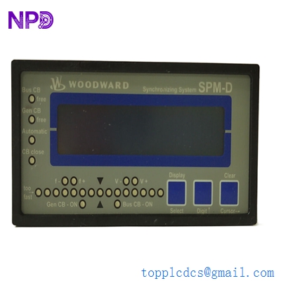
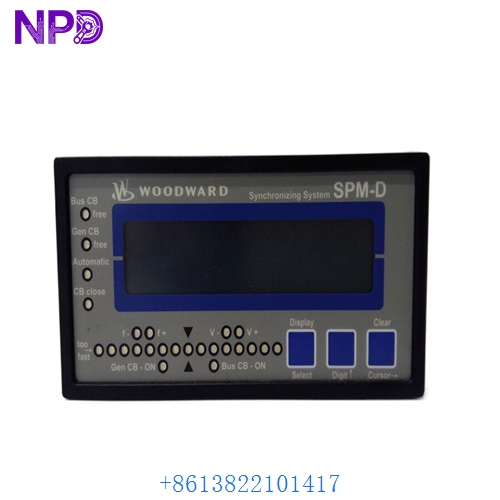
The Woodward SPM-D Synchronizer Part 5448-891 is a microprocessor-based digital synchronizer designed to automate frequency, phase, and voltage matching for three-phase AC generators. Below are the ten core specification parameters detailing its build, origin, and technical ratings:
- Brand: WOODWARD
- Model Number: 5448-891
- Series: SPM-D Synchronizer Series
- Product Name: Digital Synchronizer Module
- Place of Production: United States / Global Facilities
- Condition State: Brand New / Factory Recertified Options Available
- Dimensions: Standard Panel-Mount Form Factor (APRANORM DIN 43700, 144 × 72 × 122 mm)
- Weight: Approx. 0.8 kg (1.8 lbs)
- Country of Origin: USA
- Power Supply & Measuring Inputs: 2 VDC Power Supply, 2-phase generator voltage and 2-phase busbar voltage measuring/display, measuring inputs 1 VAC
⚙️ Operating Guidelines & Usage Methods
Proper integration of the Woodward 5448-891 synchronizer requires strict adherence to industrial electrical standards and precise wiring of potential transformers for both the generator and busbar feeds. Operators must ensure that all control and measurement wiring utilizes shielded cables to mitigate electromagnetic interference (EMI) from adjacent high-voltage lines. Grounding must be implemented strictly in accordance with manufacturer guidelines to protect internal circuitry from ground loops and voltage transients. Configuration and monitoring can be managed via the front-panel interface or dedicated software tools.
During active operation, continuous monitoring of synchronization parameters, mains failure recognition, and generator protection features (including featured options like VJH, UF, R2, and discrete speed/voltage control) is vital. Maintenance personnel should periodically inspect terminal block connections and verify that ambient operating temperatures remain within specified industrial limits. Never attempt internal component repairs or adjustments while the unit is energized, as this can cause permanent electrical damage or severe personal injury.
⚡ Power-Up & Power-Down Sequence
Industrial control hardware demands a structured sequencing protocol to prevent voltage spikes, data corruption, and out-of-phase breaker closure.
Startup Sequence:
- Verify that all external emergency stop circuits, safety interlocks, and auxiliary sensing lines are fully functional and in their normal standby states.
- Energize the control power distribution panel, ensuring the 2 VDC power supply to the module stabilizes within its operational window.
- Allow the module internal boot sequence and diagnostic self-test to complete fully, observing the digital display and status indicators.
- Bring the incoming generator up to rated speed and voltage, feeding the 2-phase generator voltage inputs (1 VAC measuring inputs) correctly.
- Enable the synchronizer control loop to monitor 2-phase busbar voltages and generator parameters using discrete raise/lower outputs before permitting breaker closure.
Shutdown Sequence:
- Disable or bypass automatic synchronizer control via operator control interfaces prior to opening generator output breakers.
- Transfer or shed active electrical load safely and open the main generator breaker.
- Command the prime mover shutdown sequence, allowing engine or turbine deceleration to a complete standstill.
- De-energize the module input power supply and potential transformer feeds by opening the main control circuit breakers.
- Lock out and tag out (LOTO) all power sources if physical maintenance or module replacement is required.
📖 Product Operating Instructions
The Woodward 5448-891 SPM-D synchronizer operates by digitally processing 2-phase generator voltage and 2-phase busbar voltage inputs (1 VAC measuring inputs) alongside featured options such as VJH, UF, R2, and discrete speed/voltage control to match frequency, phase slip, and voltage. It utilizes discrete raise/lower output bias signals to interface with compatible speed controls and automatic voltage regulators. The integrated display and LED synchronoscope provide real-time visual feedback, while built-in mains failure recognition and generator protection options safeguard the electrical infrastructure.
❓ Frequently Asked Questions (Q&A)
Q1: What should I do if the unit fails to initialize or display information upon power-up? A1: First, check the incoming power supply to ensure it is stable around the 2 VDC requirement. Verify that all terminal block connections are secure and that internal fusing has not blown. If faults persist, check for external wiring issues.
Q2: How do the 2-phase measuring inputs function on the 5448-891 model? A2: The unit features dedicated inputs for 2-phase generator voltage and 2-phase busbar voltage configured for 10 VAC / 1 VAC measuring ranges, allowing comprehensive phase and voltage comparison.
Q3: What control outputs does this specific part number utilize? A3: Part number 5448-891 comes standard with discrete raise/lower outputs for frequency and voltage adjustments, alongside integrated mains failure recognition and generator protection features.
Q4: What environmental precautions are necessary for long-term reliability? A4: Ensure the module is flush-mounted within a properly rated electrical cabinet equipped with adequate ventilation or climate control to prevent moisture condensation and maintain safe operating temperatures.