
Description
⚙️ Product Specifications (Datasheet)
| Parameter | Value |
|---|---|
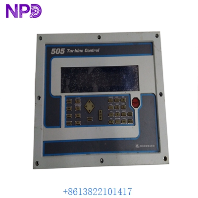
| Part Number | 8200-1302 (505D / 505 Series) |
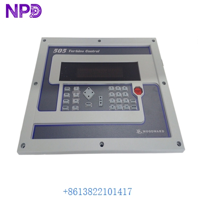
| Device Type | Integrated Graphical Front Panel Steam Turbine Digital Governor |
| Input Power Supply | Low Voltage DC (18 to 32 VDC, 24 VDC Nominal @ 40 W max) |
| Dimensions | 11.0″ H x 14.0″ W x 4.0″ D (279 mm x 356 mm x 102 mm) |
| Weight | Approx. 9.5 lbs (4.3 kg) |
| Country of Origin | USA (Woodward, Inc.) |
| Certifications & Approvals | Marine Certified (DNV/ABS) & ATEX / IECEx Zone 2 Hazardous Location |
| Integrated Display & HMI | 7.0-inch Color Graphic Screen (800×480 resolution) with softkeys |
| Communication Protocols | Ethernet (Modbus TCP, SNTP), Dual RS-232/RS-485 (Modbus RTU), CANopen |
| Actuator & Speed Inputs | 2 Actuator Outputs (4-20 mA or 20-160 mA) / 2 Speed Inputs (MPT/Proximity) |
🚀 Standard Operating Procedure
- Pre-Start Loop Checks: Inspect terminal wiring connections, confirm DC power input is stable between 18 and 32 VDC, and verify speed sensor loops and emergency trip circuit continuity.
- System Initialization: Power up the module and observe the 7.0-inch color screen as it completes internal boot diagnostics, firmware self-checks, and system safety integrity checks.
- Control Mode Verification: Choose between local panel control and remote plant control using the front panel mode selection keys or SCADA commands.
- Turbine Start Sequence: Press the front panel START button. The governor executes pre-configured speed-ramping profiles, including cold/warm/hot start curves and critical speed avoidance bands.
- Dynamic Parameter Monitoring: Track critical real-time parameters (RPM, speed setpoint, steam valve position %, auxiliary control loops) directly on the graphic screen overview dashboard.
- Load Engagement & Synchronization: Ramp up turbine speed to rated conditions and engage the generator breaker or driven load once synchronization parameters are satisfied.
- Controlled Ramp-Down & Trip: Press the STOP button to execute a controlled ramp-down to idle speed, or engage the local trip circuit when performing scheduled emergency testing.
⚙️ Parameter Configuration Guide
- Access the main menu screen by pressing the HOME or MENU softkeys on the front panel interface.
- Navigate to the “Configuration / Program Mode” menu using the directional navigation arrows and press ENTER.
- Enter the security access code (Level 1, 2, or 3 password depending on privilege requirements) when prompted.
- Scroll through parameter groups such as Speed Control Settings, Critical Speed Avoidance, Valve Calibrations, or Digital I/O Mapping.
- Highlight the targeted parameter value, press ENTER to edit, use the alphanumeric keypad to adjust values, and confirm with ENTER.
- Save changes to non-volatile flash memory prior to exiting configuration mode to retain all custom settings across power outages.
🔄 Manual / Automatic Mode Switching
- To Select Manual Mode: Press the MANUAL button on the front control panel. The corresponding LED status light illuminates, granting local operators manual authority to ramp speed setpoints and override valve positions locally.
- To Select Auto Mode: Press the AUTO button on the panel. The AUTO status LED illuminates, transferring control logic to automatic internal PID loops or external remote signals (Modbus TCP/RTU or 4–20 mA input commands from a master DCS).
❓ Frequently Asked Questions (Q&A)
- Q: What makes model 8200-1302 suitable for marine and hazardous environments? A: Model 8200-1302 is engineered with marine classification society approvals (such as DNV and ABS) and holds ATEX/IECEx Zone 2 ratings, allowing installation in marine vessel engine rooms and potentially explosive industrial atmospheres.
- Q: How does the integrated 7-inch color graphic panel differ from older 505 models? A: Unlike legacy text-line units, the 505D graphical front panel displays live trend curves, dynamic valve charts, alarm logs, and real-time operational diagrams directly on screen without needing external software for basic diagnostic visibility.
- Q: What is the purpose of the dual speed sensor inputs? A: The dual speed channel architecture provides redundant speed sensing (supporting magnetic pickups or proximity probes), ensuring high availability, peak detection accuracy, and instant overspeed shutdown protection.