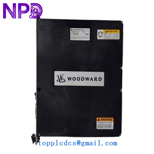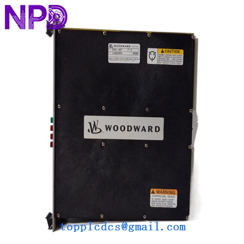

Description
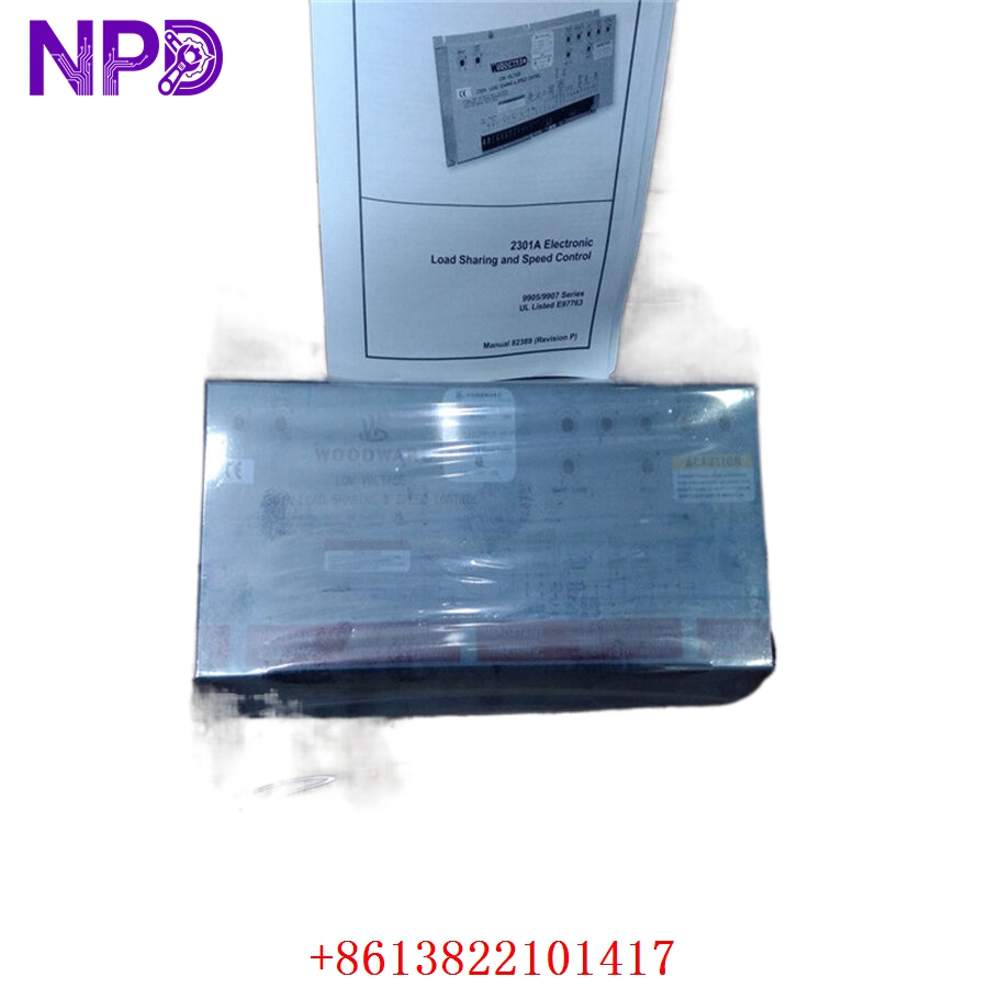
- Model: Woodward 9907-164 (Peak 150 Series)
- Brand: Woodward (USA)
- Series: Peak 150 Digital Control for Steam Turbines
- Core Function: Microprocessor-based digital governor controlling steam turbine speed and driving actuator positioning
- Product Type: Digital Control Governor / Turbine Controller
- Key Specs: 24 VDC Power Input | Dual Magnetic Pickup (MPU) Channels | 4 to 20 mA Actuator Driver Port | Modbus RTU Protocol
- Operating Input Power: 18 to 32 V DC (Nominal 24 V DC, 30 W maximum power consumption)
- Speed Sensing Channels: 2x independent high-frequency Magnetic Pickup (MPU) inputs (1 to 30 Vrms)
- Speed Range Capacity: 400 Hz to 15,000 Hz internal input tracking limit
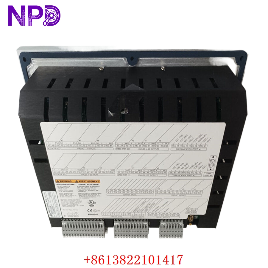
- Actuator Signal Output: 1x dedicated, isolated output port configured for 4 to 20 mA or 0 to 200 mA actuator coils
- Discrete Input Channels: 8x programmable contact inputs (internally powered with 24 V DC wetting voltage)
- Discrete Output Channels: 4x programmable Form C relay outputs (rated at 5 A at 28 V DC or 250 V AC)
- Analog Monitor Interface: 3x programmable 4 to 20 mA analog outputs for speed, valve position, or load tracking
- Serial Communications Port: 1x multi-drop RS-485 port supporting Modbus RTU protocol
- Enclosure Specifications: NEMA 4X front panel keyboard protection rating when flush-mounted in a control cabinet door


Application Scenarios & Engineering Pitfalls
The On-Site Reality
In critical thermal process setups, a steam turbine isn’t something you can just cycle off and on when a component acts up. The Woodward 9907-164 controls the steam admission valves that govern turbine speed. If this digital governor suffers an internal fault or loses its speed sensing inputs, the system drops into an emergency trip sequence, shutting down downstream generators or high-capacity compressors. Since the Peak 150 line is no longer supported by current Woodward assembly operations, securing an immediately deployable, fully tested module is the only way to avoid extended, multi-week plant outages.
Typical Deployment Scenarios
- Power Generation – Industrial Co-Generation Steam Turbines
Maintains tight generator synchronization and handles load control routines while managing process steam extraction loops.
- Petrochemical – Compressor Mechanical Drive Applications
Controls turbines driving critical process gas compressors, adjusting mechanical speed dynamically based on upstream pressure changes.
- Pulp and Paper – Boiler Feed Fan Prime Movers
Regulates small to mid-sized mechanical-drive steam turbines under constant thermal changes, ensuring uninterrupted draft airflow.
- Marine Systems – Auxiliary Turbogenerator Control
Ensures precise speed and load governing on shipboard steam generator units operating in high-vibration engine room settings.
Plant Survival Case Study: Paper Mill Turbo-Generator Emergency
- Background: A large paper plant in the Southeast utilized a legacy utility steam turbine driven by a Woodward Peak 150 governor (9907-164) to offset factory electrical power costs and supply process steam.
- The Problem: During a seasonal plant startup sequence, the active 9907-164 controller’s display went completely blank due to an internal power-stage breakdown. Without the governor, the turbine could not be rolled, depriving the facility of both auxiliary power and the low-pressure steam required for the paper drying line. The local distributor noted the unit was obsolete with an open-ended lead time for factory-remanufactured alternatives, exposing the mill to substantial daily utility costs.
- The Solution: The automation project engineer bypassed typical supply blockages by contacting our facility directly. We pulled a pristine, legacy-surplus 9907-164 controller from our warehouse inventory, ran it through our rigorous speed-loop simulation and relay stress configurations, and shipped it out via overnight express.
- The Result: The unit arrived at the plant gate early the next morning. The plant maintenance team mounted the housing, inputted the archived tuning constants, and completed the turbine startup loop before noon. The mill avoided an extended shutdown window and restored full process steam delivery to the drying machinery.
Compatible Replacement Models
When maintaining vintage turbine control hardware, cross-referencing functional suffix codes prevents field mounting mismatches. Here is the migration and compatibility map for this module family:
| Original Part Number | Alternative Model | Compatibility Level | Key Differences / Structural Variances | Required On-Site Modification Steps | Cost Variance |
| 9907-164 | 9905-048 | ⚠️ Software Compatible | Standard Peak 150 chassis architecture but utilizes a 120 V AC / 240 V AC integrated power block instead of a 24 V DC input line. | Requires routing a dedicated AC line inside the control panel and altering terminal power land connections. | -10% |
| 9907-164 | 9907-164 Revision Base | ✅ Drop-in Replacement | Exact hardware build and engineering lineage match; contains standard 24 V DC board architecture and the same terminal pin assignments. | Direct swap. Mount the chassis, plug in terminal strips, and manually key in the specific system parameter set. | Baseline Cost |
| 9907-164 | Peak 200 Series | ❌ Hardware Incompatible | Next-generation digital platform with a completely different footprint, graphical display, and configuration tools. | Requires systematic control panel reconstruction. All field wires must be remapped, and the system requires a fresh application design. | +180% |
Quality Assurance & Testing Standard Operating Procedure
To address the reliability demands of safety-critical turbine systems, every single Woodward governor undergoes a documented, multi-point functional verification process before being packaged and cleared for site shipment.
[Inbound Serialization Log] ➔ [Optical Solder/Capacitor Inspection] ➔ [High-Voltage Insulation Check] ➔ [Dual-MPU Closed-Loop Speed Simulation] ➔ [ESD Safe Sealed Packing] 1. Inbound Serialization & Visual Verification
- Authenticity Profiling: Verifying the physical manufacturer nameplate, internal board traces, and firmware version structures against Woodward’s production history.
- Chassis Assessment: Inspecting the front panel keyboard membrane, terminal connectors, and housing frame for structural defects or wear.
2. Optical Component and Substrate Inspection
- Solder Joint Review: High-magnification microscopic tracking of all PCB traces and power component connections to check for micro-fracturing from machine room vibration.
- Capacitor Lifecycle Audit: Detailed review of internal power supply filtering capacitors to ensure zero degradation, swelling, or internal leakage.
3. Galvanic Isolation Circuit Verification
- Dielectric Isolation Testing: Applying a 500 V DC test barrier between the primary 24 V DC power inputs, discrete relay lines, and ground grounding points using a Fluke 1507 insulation tester.
- Pass Threshold: Isolations must measure above 10 MΩ to ensure field spikes cannot bridge into the core microprocessor logic.
4. Dual-MPU Closed-Loop Speed Simulation
- The Testing Environment: The Woodward 9907-164 is mounted into a specialized testing rack linked to a high-frequency signal generator loop mimicking two magnetic pickups on a turbine shaft.
- Dynamic Actuator Loop Verification: We simulate turbine startup, idle ramp, rated speed governing, and overspeed trip tests. The 4 to 20 mA actuator driver output port is paired with a physical electronic load cell to confirm precise, jitter-free current delivery across its entire range.
- Relay Output Exercising: Cycling all Form C alarm and trip relays under structural load conditions to confirm crisp contact engagement.
5. Final Quality Sign-Off and Secure Packaging
- Certification Labeling: The testing engineer signs and applies a dated, serialized “QC Passed” seal over the anti-static enclosure layer.
- ESD Shielding Protocol: The controller is sealed inside an industrial-grade anti-static, moisture-barrier bag filled with fresh desiccant packs.
- Mechanical Protection: Housed inside tailored high-density foam padding inside double-walled corrugated shipping cartons to eliminate transportation vibration risks.
High-Availability Governor Troubleshooting Quick Reference
❗ SAFETY FIRST: Never attempt to adjust control parameters or clear hard trip codes while the turbine is running under manual control without secondary mechanical overspeed protection active. An uncontrolled turbine runaway can cause catastrophic structural failure and severe physical injury.
Q: The controller boots up completely but displays a persistent, flashing “Speed Signal Fault” error, even though the turbine shaft is visibly spinning.
A: Correlation: High. This typically points to either a failing MPU sensor out in the field or a breakdown within the speed detection processing circuits on the 9907-164 input board.
- Use a digital multimeter set to AC Volts to measure the signal directly across the MPU input terminals while the turbine is turning. The voltage must register >1.0 Vrms.
- Check the signal frequency; it should correspond to your target gear tooth count ((RPM \times Teeth) / 60).
- If the signal voltage and frequency check out at the terminal screws but the governor display reads zero speed, the input conditioning circuit on the board has failed. Swap out the governor unit.
Q: The turbine exhibits severe speed hunting or governor oscillations as soon as it transitions from idle speed into active load-governing mode.
A: Correlation: Medium-Low (Usually software tuning or actuator matching). Before condemning the board hardware, verify your internal dynamic tuning constants.
- Check the Proportional (P), Integral (I), and Derivative (D) gain variables inside the program configuration menus. If a battery backup has failed over a long power outage, these values may have reverted to factory defaults.
- If the PID settings match your historical commissioning datasheets perfectly, inspect the actuator output lines. High-frequency analog output ripple from a failing DAC stage on the board can cause the valve to jitter. If you detect analog noise on the actuator lines, replace the controller.
Q: The governor panel screen stays completely dead when the main panel circuit breaker is engaged, but adjacent 24 V DC modules power up normally.
A: Correlation: High. The internal switched-mode power supply (SMPS) block or input protection diode on the 9907-164 card has failed due to a localized line spike.
- Verify that the incoming voltage measures between 18 and 32 V DC right at the controller’s power terminals.
- If power is present but the front panel display and internal LEDs show no signs of life, the internal power supply module is damaged. Replace the entire governor assembly.
❗ Critical Field Installation Checklist for Plant Technicians
- Document and Backup Configuration Parameters: Do not disconnect the old governor without backing up your parameters. The Peak 150 stores dozens of site-specific constants (e.g., gear teeth configuration, idle/rated speeds, PID variables). Record every single value from the front display menu of the old unit before pulling it. You will need to manually program these exact values into the replacement module before starting the turbine.
- Twisted-Pair MPU Shielding: Ensure that the wiring lines from the magnetic speed sensors are routed using high-quality twisted-shielded cables. Ground the shield drain wire at the governor panel chassis end only. Running unshielded speed lines near high-voltage motor cables can inject noise, causing erratic speed tracking or unexpected overspeed trips.
- Confirm Actuator Coil Current Match: Verify that the internal jumper block configuration on the new module matches the current requirements of your physical valve actuator coil (4 to 20 mA vs. 0 to 200 mA). Driving a low-impedance 200 mA coil with the jumper set for a standard 20 mA loop will overload the driver circuit, leading to a sudden loss of valve control.