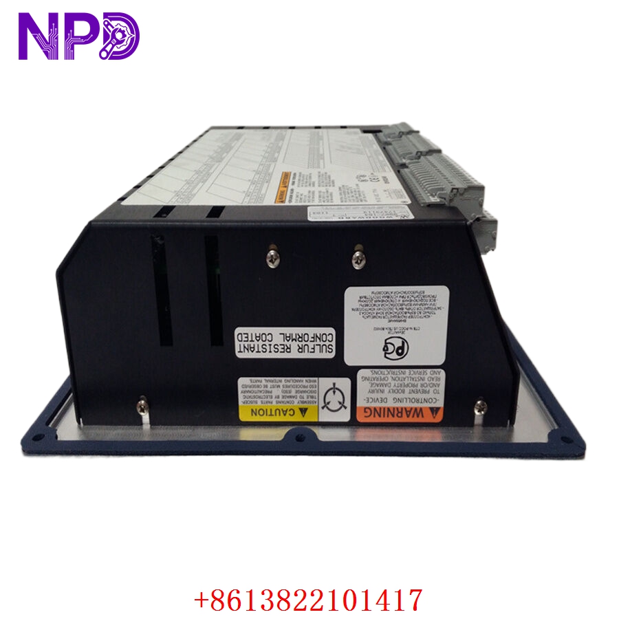
Description
- Model: WOODWARD 9907-164
- Brand: Woodward (USA)
- Series: 505 / 505E Digital Governor Series
- Core Function: Steam turbine speed and load control
- Product Type: Digital Governor Controller Module
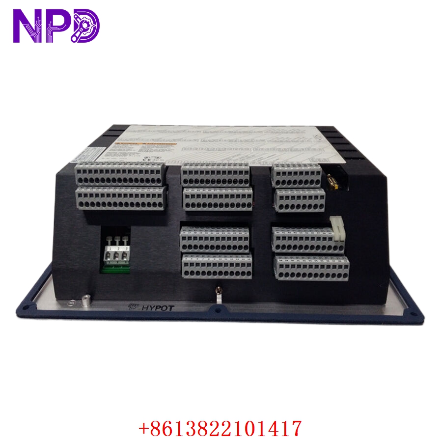
- Key Specs: 24 V DC input, 16 discrete inputs, Modbus RS-232/RS-422
This model has been widely deployed in steam turbine applications across refineries, utility plants, fertilizer facilities, and compressor stations. Even now, many plants still keep it on their strategic spare parts list because replacing the entire governor system costs far more than maintaining legacy hardware. In my experience, facilities with 15+ year old turbines usually keep at least one buffer stock unit on-site to avoid extended outages.
The 9907-164 belongs to Woodward’s mature 505 governor family. Market availability today mainly comes from surplus inventory channels rather than fresh factory production. That changes the purchasing strategy completely…
For critical turbines:
- Keep 1–2 units as insurance stock
- Store in climate-controlled cabinets
- Perform annual power-up verification
- Record firmware and DIP switch settings before installation
A last-time-buy strategy makes sense here, especially for plants planning to keep legacy steam turbines operational for another 5–8 years.

Key Technical Specifications
- Input Voltage: +24 V DC at 1 A
- Display Interface: Two-line LCD, 24 characters per line
- Keypad Type: 30-key multifunction keypad
- Discrete Inputs: 16 contact inputs (4 dedicated, 12 programmable)
- Analog Inputs: 6 programmable 4–20 mA current inputs
- Communication Ports: RS-232 and RS-422
- Supported Protocol: Modbus communication
- Control Capability: Single extraction/admission steam turbine control
- Operating Temperature: -20 °C to +60 °C
- Storage Temperature: -40 °C to +85 °C
- Protection Rating: IEC 60529 IP56
- Software Compatibility: 505View or OpView™
- Weight: Approximately 4.1 kg (9.11 lb)
- Mounting Type: Panel-mounted governor controller
- Diagnostic Features: First-out shutdown indication, self-diagnostics, critical speed avoidance
- Output Functions: Valve positioning and turbine actuator control
Technical data compiled from multiple industrial surplus references and field listings.
Installation & Configuration Guide
Pre-Installation Preparation (Estimated Time: 10 Minutes)
⚠️ Safety First
- Notify operations personnel before turbine shutdown
- Confirm turbine is in safe standby condition
- Disconnect governor control power supply
- Wait at least 5 minutes for internal capacitors to discharge
Required Tools:
- Anti-static wrist strap
- PH1 screwdriver
- Fluke 115 multimeter
- Label markers
- Laptop with 505View or OpView software
- USB backup storage
Before removing the old controller, always:
- Export current governor configuration
- Photograph terminal wiring
- Record DIP switch positions
- Save alarm logs if available
Honestly… this step gets skipped too often during emergency shutdowns, and that usually creates more downtime later.
Removing the Existing Module (Estimated Time: 5–10 Minutes)
- Remove front terminal cover carefully
- Label all field wiring before disconnecting
- Loosen terminal screws counterclockwise
- Disconnect communication cables separately from analog I/O
- Release mounting hardware and remove controller vertically
⚠️ Important:
Do not pull wiring harnesses aggressively. Older turbine cabinets often have brittle terminal insulation after years of heat exposure.
Inspect:
- Connector pins
- Backplane condition
- Ground continuity
- Moisture or corrosion traces
If corrosion appears around analog terminals, clean using approved contact cleaner before installing the replacement unit.
Installing the New Module (Estimated Time: 10 Minutes)
- Wear anti-static protection before opening packaging
- Verify model number matches exactly: 9907-164
- Confirm firmware compatibility
- Restore DIP switch configuration
- Install module firmly into mounting position
- Reconnect wiring using previous labels
- Tighten terminals evenly
Typical Configuration Items:
- Node address
- Modbus baud rate
- Turbine speed scaling
- Valve travel limits
- Shutdown logic
- Redundant trip settings
Self-check before power-up:
- Ground connected
- No loose wires
- Communication cable secured
- Analog loops verified
- DIP switches confirmed
- Shield drain grounded properly
Power-On & Functional Testing (Estimated Time: 15 Minutes)
Before applying power:
- Measure incoming supply voltage
- Confirm 24 V DC ±10%
- Verify insulation resistance exceeds 10 MΩ
Power-up sequence:
- Energize controller cabinet only
- Observe startup LEDs
- Verify keypad response
- Connect engineering workstation
- Read controller diagnostics
- Confirm communication handshake