
🔹 Product Description
The WOODWARD 9904-1533 is a hydraulic Inlet Guide Vane (IGV) Actuator designed for industrial gas turbine control systems. It is associated with GE part number 362A5051P001 and is used to regulate the position of turbine inlet guide vanes.
The actuator provides precise hydraulic positioning through an electrohydraulic servo valve and position feedback system. It supports accurate adjustment of inlet airflow during different turbine operating conditions, helping maintain stable turbine performance and efficient operation.
The 9904-1533 features a double-acting hydraulic design and an integrated servo valve assembly. It is suitable for demanding industrial turbine applications where reliable actuator response and accurate position control are required.
Key applications include:
- GE industrial gas turbine systems
- Inlet guide vane positioning
- Turbine airflow regulation
- Power generation facilities
- Industrial turbine control systems
- Electrohydraulic control applications
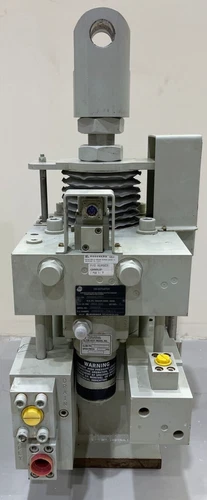
⚙️ Product Datasheet & Parameters
- Brand: WOODWARD
- Model: 9904-1533
- GE Part Number: 362A5051P001
- Series: Woodward IGV Actuator
- Product Name: Hydraulic Inlet Guide Vane Actuator
- Place of Manufacture: United States (manufacturer origin; verify individual unit)
- Product Status: New – Open Box (according to the supplied listing information)
- Dimensions: Exact overall dimensions require the model-specific outline drawing
- Weight: Approximately 221 kg (487 lb), reference actuator configuration
- Country of Origin: United States (verify individual unit nameplate)
- Actuator Stroke: 1.88 inches (47.8 mm)
- Cylinder Bore: 6.250 inches (158.75 mm)
- Rod Diameter: 2.500 inches (63.50 mm)
- Hydraulic Operating Pressure: 1,400–1,800 psig
- Hydraulic Fluid: Petroleum-based or approved fire-resistant hydraulic fluid
- Servo Valve Flow Rating: 10 US gal/min (38 L/min) at 1,000 psid valve pressure drop
- Electrical Input: ±8 mA reference rating
- Position Feedback: LVDT
- Sealing Material: Viton elastomer
- Discontinued Status: Exact lifecycle status requires confirmation from Woodward using the serial number
🔧 Daily Maintenance and Care
- Inspect the actuator housing for corrosion, cracks, and external damage.
- Check hydraulic connections and fittings for leakage.
- Monitor hydraulic pressure during normal turbine operation.
- Inspect hydraulic fluid condition and maintain the specified cleanliness level.
- Check the hydraulic filter and replace it according to the maintenance schedule.
- Inspect servo valve connections and electrical wiring.
- Monitor LVDT feedback signals for stability and accuracy.
- Check actuator movement for abnormal noise, vibration, or hesitation.
- Inspect mounting bolts and mechanical linkages.
- Record actuator position, operating pressure, and response time.
- Inspect hydraulic seals for deterioration.
- Maintain maintenance records and monitor changes in operating performance.
🛠️ Troubleshooting and Common Problems
1. Actuator Does Not Move
- Check hydraulic supply pressure.
- Inspect hydraulic lines and valves.
- Verify servo valve electrical input.
- Check turbine control system output signals.
- Inspect the actuator for mechanical obstruction.
2. Incorrect IGV Position Feedback
- Inspect LVDT wiring and connectors.
- Check feedback signal stability.
- Verify LVDT calibration.
- Inspect mechanical linkage alignment.
- Check the control system position feedback configuration.
3. Slow Actuator Response
- Check hydraulic fluid temperature and viscosity.
- Inspect the hydraulic filter for blockage.
- Verify operating pressure.
- Check servo valve performance.
- Inspect internal leakage and hydraulic seals.
4. Hydraulic Leakage
- Inspect hydraulic fittings and connections.
- Check O-rings and sealing surfaces.
- Examine the actuator rod seal.
- Verify hydraulic pressure is within the specified range.
- Replace damaged seals using approved service procedures.
5. Servo Valve Fault
- Check electrical connections.
- Verify the input current signal.
- Inspect hydraulic fluid cleanliness.
- Check servo valve response and internal leakage.
- Have the servo valve inspected by qualified service personnel.
6. Unstable IGV Position
- Inspect LVDT feedback signals.
- Check hydraulic pressure fluctuations.
- Examine mechanical connections.
- Verify controller tuning and position demand signals.
- Check for air contamination or hydraulic fluid degradation.
7. Actuator Fails to Reach Full Stroke
- Verify available hydraulic pressure.
- Inspect mechanical travel restrictions.
- Check servo valve operation.
- Examine internal hydraulic leakage.
- Confirm that the actuator stroke and control settings are correct.
⚠️ Safety Precautions
- Installation and maintenance must be performed by qualified turbine and hydraulic technicians.
- Isolate the turbine and follow the approved lockout/tagout procedure before servicing.
- Release hydraulic pressure before disconnecting hydraulic lines.
- Never loosen hydraulic fittings while the system is pressurized.
- Use hydraulic fluid approved for the actuator.
- Maintain the specified hydraulic fluid filtration and cleanliness.
- Do not exceed the rated hydraulic operating pressure.
- Protect LVDT wiring and servo valve electrical connections.
- Keep hands clear of moving actuator linkages.
- Verify actuator calibration and full-stroke operation before returning the turbine to service.
- Follow the applicable Woodward and GE turbine maintenance procedures.
⭐ Recommended WOODWARD Models
- 9904-1533 – IGV Hydraulic Actuator
- 9904-1532 – IGV Actuator
- 9904-1448 – IGV Actuator
- 9904-1371 – IGV Actuator
- 9904-989 – IGV Actuator
- 9904-533 – IGV Actuator
- 9907-018 – Speed Control Component
- 9907-164 – Governor Control Component
- 9907-167 – Governor Control Component
- 9907-175 – Control System Component
- 9907-205 – Governor Control Component
- 505XT – Digital Turbine Control
- 505E – Digital Turbine Control
- 2301A – Load Sharing and Speed Control
- 723PLUS – Digital Control System


