Description
- Product Parameters
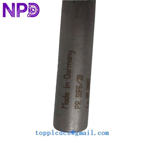
- Model Number: PR9376/20 (Often part of the Emerson/EPRO MMS 6000 series)
- Measurement Principle: Non-contact Hall Effect (Differential sensor)
- Triggering: Ferromagnetic target marks (Gear teeth, slots, or steel trigger wheels)
- Frequency Range: 0 to 12 kHz (Covers very low to high speeds)
- Response Time: < 1 µs (Pulse rise/fall time)
- Output Signal: Push-pull output (Square wave), High > 10V / Low < 1V (at 12V supply)
- Operating Voltage: 10 to 30V DC
- Air Gap: 1.0 mm (Module 1) to 1.5 mm (Module ≥ 2)
- Environmental Rating: IP67 / Hermetically sealed stainless steel housing
- Operating Temperature: -30°C to +100°C (-22°F to +212°F)
- Weight: ~410g (including standard 3m cable and mounting kit)
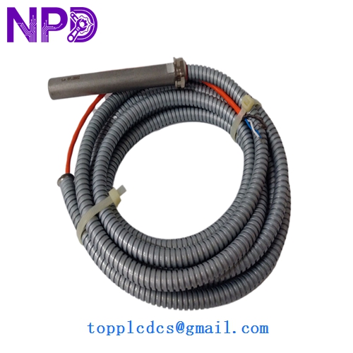
The EPRO PR9376/20 is a rugged, non-contact Hall Effect speed sensor primarily used for monitoring turbomachinery, including steam, gas, and hydro turbines, as well as compressors and large pumps. Unlike eddy current sensors that measure displacement, the PR9376 is optimized for frequency-based speed and phase measurements. Its differential Hall-effect design allows it to detect the passage of gear teeth or “key phasor” marks with high precision, providing a steep-edged square wave pulse that is ideal for digital tachometers and machine protection systems like the MMS 6000.
-
EPRO PR937620
EPRO PR937620
-
Model Comparison
The PR9376/20 is the updated version of the legacy PR9376/00 series. While both share the same 14mm diameter stainless steel body, the “20” series features a refined digital signal processor (DSP) that improves noise immunity and allows for a more stable output at extremely low speeds (near zero Hz). The PR9376/010-xxx variants usually signify different cable options, such as armored PTFE cables for high-temperature or mechanically demanding environments, whereas the standard PR9376/20 typically comes with a high-quality 3-meter or 5-meter integrated cable.
Operation Tips
- Target Material: Only use magnetically soft iron or steel (e.g., ST37). The sensor will not reliably detect non-magnetic stainless steel or aluminum targets.
- Orientation Mark: The sensor has a specific orientation mark on the housing. Ensure this mark is aligned parallel to the direction of the gear’s rotation to ensure the differential Hall elements trigger correctly.
- Gap Setting: Use a non-magnetic feeler gauge to set the air gap. For a standard Module 1 gear, a 1.0 mm gap is recommended; exceeding 2.0 mm will likely lead to pulse skipping or signal loss at high frequencies.
- Installation Safety: Avoid “hot-plugging” the sensor if possible. While it is short-circuit proof, powering the sensor after it is positioned near the target allows the internal electronics to auto-calibrate the trigger levels for optimal performance.
- Cleaning: Keep the sensor face free of metallic debris. Because it contains internal magnets, it can attract fine iron filings which may distort the magnetic field and cause “ghost” pulses.