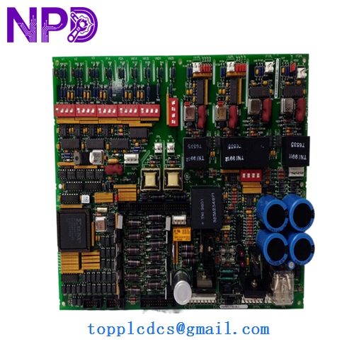

Description
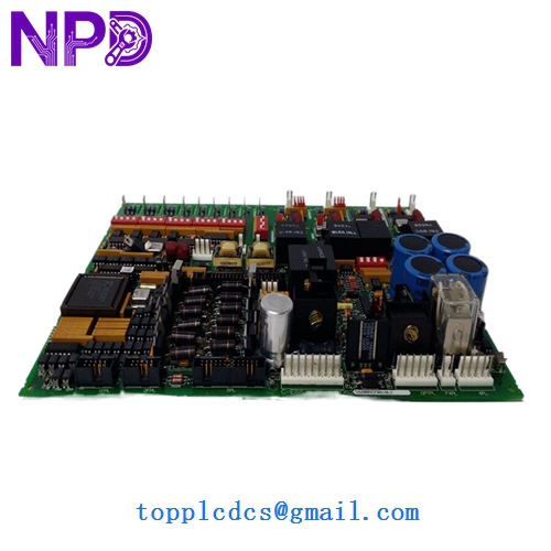
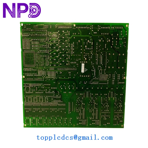
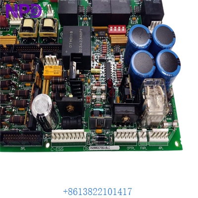
- Model: DS200DCFBG1BLC
- Brand: GE (General Electric)
- Series: Mark V Speedtronic / Innovation Series Drives
- Core Function: DC Power Supply and Voltage/Current Feedback Board
- Condition: New Surplus (Original factory stock, verified non-refurbished)
- Type: Feedback Interface Board
- Key Specs: Compatible with Mark V LM and Innovation Series cabinet architectures
- Function: Processes voltage and current feedback signals from the bridge and motor for the drive controller.
- Power Distribution: Provides regulated DC control power to other boards within the drive rack.
- Circuitry: Includes sophisticated attenuation circuits to scale high-voltage bridge signals down to logic levels.
- Connectors: High-retention ribbon cable headers for interfacing with the DSP and Power Conversion boards.
- Diagnostic Points: Built-in test points for manual multimeter verification of control voltages.
- Protection: Integrated fused circuits to protect downstream logic from power surges.
- Design Revision: G1 (Group 1) BLC version—ensure this matches your specific cabinet revision.
GE DS200DCFBG1BLC
GE DS200DCFBG1BLC
Installation & Configuration Guide
Phase 1: Pre-Installation (15 Minutes)
⚠️ Safety Protocol:
- This board interacts with high-voltage DC circuits. Power must be completely locked out (LOTO) for at least 10 minutes to allow capacitors to discharge.
- Verify the DC bus voltage is at 0V using a certified high-voltage probe before touching any terminals.
- Use a grounded ESD wrist strap; the CMOS logic on this board is highly sensitive.
Phase 2: Removal of Faulty Board (10 Minutes)
- Label all ribbon cables and individual wires connected to the DS200DCFBG1BLC.
- Carefully disconnect the cables. If the connectors feel “stuck,” do not force them; check for side-locking tabs.
- Remove the screws from the nylon standoffs.
- Inspect the area for any signs of “arcing” or burnt components on the backplane or adjacent boards.
Phase 3: Installing the New DS200DCFBG1BLC (15 Minutes)
- Jumper Configuration: This is the most critical step. Compare the hardware jumpers (e.g., JP1, JP2) on the new board with your old one. These jumpers define the feedback scaling—incorrect settings can cause an overvoltage trip on startup.
- Mounting: Secure the board onto the standoffs. Ensure it is level and not under mechanical stress.
- Reconnection: Firmly seat all ribbon cables. Ensure the red stripe on the cable aligns with Pin 1 on the header.
Phase 4: Commissioning & Validation (20 Minutes)
- Cold Check: With power still off, verify continuity of the fuses on the new board.
- Initial Power-Up: Apply control power only (if possible). Verify the diagnostic LEDs are lit in the correct sequence.
- Calibration: Use the Mark V <I> operator interface or Toolbox software to monitor the feedback values.
- Functional Test: Slowly ramp the drive and verify that the “Feedback Voltage” in the software matches the actual DC bus voltage measured with a meter.
Customer Cases & Industry Applications
Case 1: Paper Mill Drive Failure A high-speed paper machine in Georgia experienced a sudden drive trip during a grade change. Diagnostics pointed to a failure in the feedback loop on the DS200DCFBG1BLC. The mill was losing $5,000 per hour in production. We provided a New Surplus board from our inventory. By swapping the board and matching the jumpers, the mill was back at full speed in under 3 hours, avoiding a massive production deficit.
Case 2: Steel Plant DC Motor Control A massive DC motor used in a rolling mill was exhibiting unstable speed control. The issue was traced to “noise” in the feedback signal originating from an aged DS200DCFBG1BLC board. Replacing the unit with our “New Surplus” stock stabilized the signal and improved the surface quality of the steel being produced. In my experience, these feedback boards are wear-items in high-heat steel environments.
Frequently Asked Questions (FAQ)
Q: What is the difference between the G1 and G2 versions of this board? A: In my experience, G1 and G2 refer to specific hardware “Groups.” While they often perform the same function, they may have different attenuation resistors for different motor frame sizes. You should always try to match your Group (G1) exactly to avoid calibration headaches.
Q: Does the board come with the EPROM chips installed? A: This board is primarily analog and hardware-logic based, but if your specific revision uses socketed chips, you should move the original chips from your old board to the new one to maintain your specific software parameters.
Q: Why buy “New Surplus” for an older Speedtronic system? A: GE has largely transitioned to newer platforms, making original Mark V parts expensive and slow to ship from the factory. Our New Surplus units are original GE factory-built boards that have never been used. You get “factory new” reliability without the 20-week lead time.
Q: Can I repair my old DS200DCFBG1BLC? A: While possible, it is risky for feedback circuits. If a resistor has drifted due to heat, your feedback will be inaccurate, leading to motor instability. For critical turbine or drive applications, replacing the board with a verified New Surplus unit is the safer, more professional choice.
Q: How do I know if the board is compatible with my drive? A: Look for the full part number on the silk-screened edge of your board. If it says DS200DCFBG1BLC, it is a 100% match. The “BLC” suffix denotes the specific revision of the layout—later revisions like “C” are usually backward compatible with “A” or “B” versions.