Description
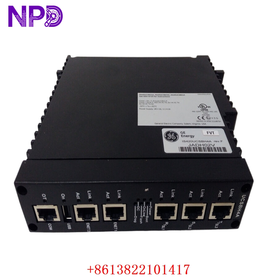
The GE IC800SSI228RD2-CE is a specialized high-speed counter and interface module within the GE (now Emerson/Automation) VersaMax I/O family. This module is designed to provide precise measurement and control for applications involving high-speed pulse trains, such as those generated by encoders, flow meters, or rotational sensors. It enables the VersaMax controller to process high-frequency signals with minimal latency, ensuring synchronization in motion control and high-speed counting tasks.
Technical Specifications
| Parameter | Detail |
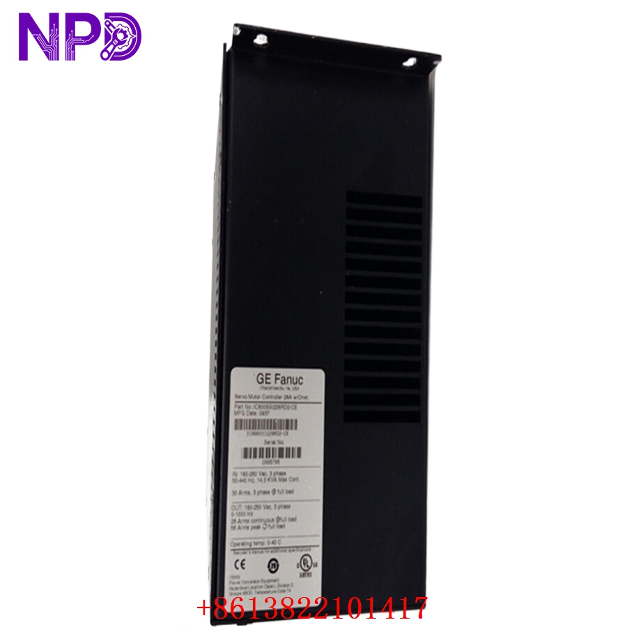
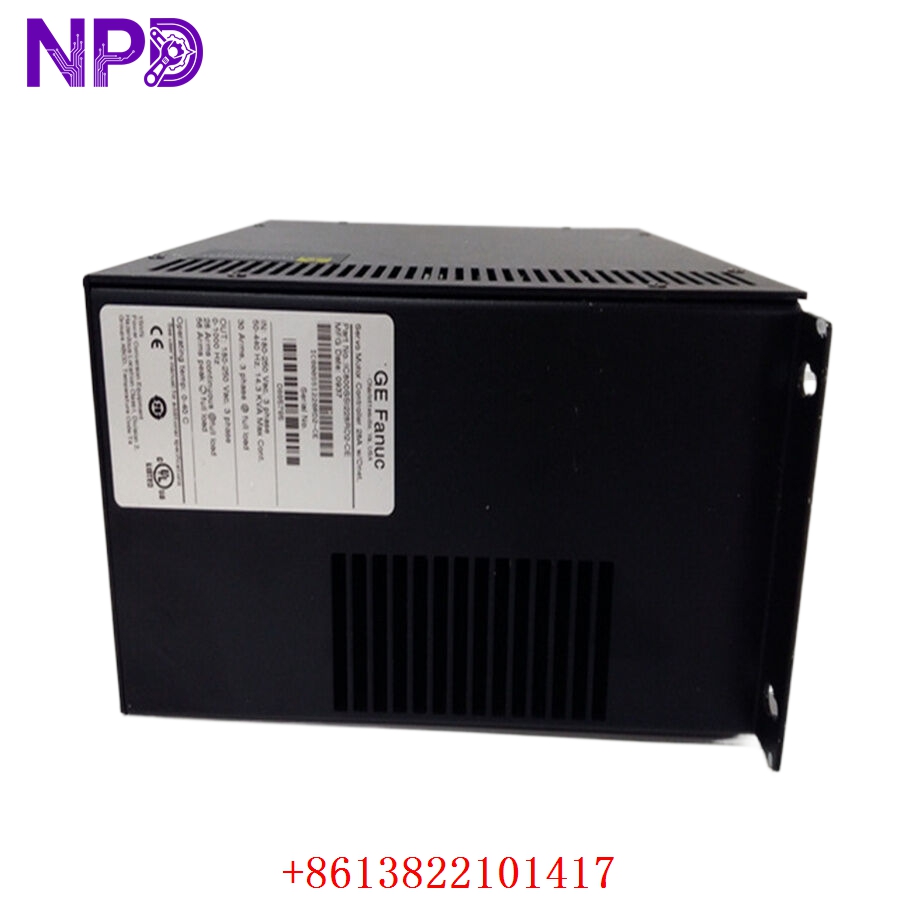
| Model | IC800SSI228RD2-CE |
| Manufacturer | GE (Emerson Automation) |
| Device Type | High-Speed Counter / SSI Interface |
| Compatibility | VersaMax I/O System |
| Input Type | High-frequency pulse / SSI (Synchronous Serial Interface) |
| Mounting | DIN Rail (VersaMax Backplane) |
| Operating Temperature | 0°C to 60°C |
Fields of Application
The IC800SSI228RD2-CE is deployed in industrial scenarios requiring exact position or rate tracking:
- Motion Control: Interfacing with absolute encoders to track motor shaft position.
- Flow Measurement: Calculating totalized flow from high-frequency pulse-output flow meters.
- Packaging and Assembly: Tracking high-speed product movement for labeling or reject mechanisms.
- Printing Machinery: Monitoring roller synchronization and web registration.
Product Introduction
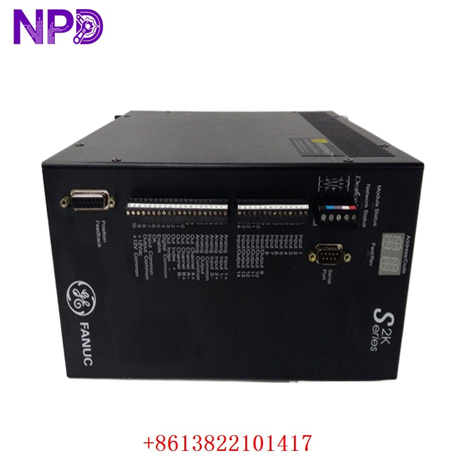
This module acts as the “encoder specialist” for the VersaMax system. By offloading the burden of pulse counting and SSI data decoding from the main CPU, the module ensures that critical timing data is captured accurately even if the main controller is busy with other background tasks. It supports SSI protocol, allowing it to communicate with absolute encoders to provide exact position data immediately upon system startup, which is critical for machines that require an immediate “homing” state.
Product Use Instructions
To integrate the IC800SSI228RD2-CE:
- Ensure the power to the VersaMax I/O rack is disconnected.
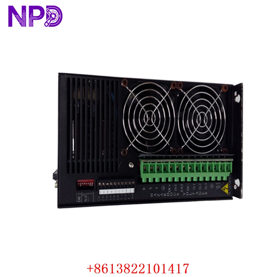
- Snap the module onto the standard DIN rail and ensure it clicks into the backplane connector.
- Wire the encoder/sensor signals to the appropriate terminal blocks on the module faceplate, ensuring that signal shielding is grounded at the source to prevent electromagnetic interference.
- Power up the system and open the configuration software (e.g., Proficy Machine Edition).
- Add the module to the I/O configuration tree and set the input parameters (e.g., count mode, SSI clock rate, pulse scaling).
- Download the configuration and monitor the “Input Count” or “Position Value” register in the controller’s memory map.
Product Use Precautions
High-speed pulse signals are extremely sensitive to electrical noise; always use twisted-pair, shielded cabling and ensure the shield is terminated at the module’s ground terminal. Do not exceed the voltage ratings of the input ports, as this will destroy the high-speed optocouplers. Keep the I/O rack cooling clear, as high-frequency processing generates internal heat that can lead to data drift if the module exceeds its operating temperature. Always back up your configuration file after fine-tuning the pulse-scaling factors.
Frequently Asked Questions (Q&A)
Q: What is the main difference between this module and a standard digital input?
A: A standard digital input is sampled at the scan rate of the CPU (typically milliseconds), which is far too slow for high-speed pulse tracking. The IC800SSI228RD2-CE uses dedicated hardware hardware logic to sample inputs at much higher frequencies (microsecond resolution).
Q: Can I use this with non-SSI encoders?
A: The module is specifically designed to handle SSI and pulse train inputs. Ensure your sensor’s output signal type matches the module’s configurable input mode before wiring.
Q: How do I troubleshoot a “Count Mismatch” error?
A: First, check for electrical noise by monitoring the input signal with an oscilloscope. Next, verify that the scaling factor in your configuration software matches the physical resolution of your encoder (e.g., pulses per revolution).
Product Operation Methods
The module functions by continuously updating a internal buffer with the current position or count. The PLC program simply reads this register address to get the latest position. In SSI mode, the module acts as the “master,” sending a clock signal to the encoder and shifting in the data bits provided by the encoder. This whole process happens independently of the PLC scan cycle, ensuring the data is always fresh and updated at the highest possible speed.