Description
- Model: GE VMIVME-3122
- Brand: GE Fanuc / VMIC (now Abaco Systems)
- Series: VMEbus Components
- Core Function: High-speed, high-density 16-bit analog-to-digital conversion
- Product Type: Scanning Analog Input Board
- Key Specs: 64 Single-ended or 32 Differential channels | 16-bit ADC | VMEbus compatible
- Resolution: 16-bit A/D conversion
- Channel Count: 64 Channels (Single-ended) or 32 Channels (Differential)
- Input Ranges: Programmable (±10V, ±5V, ±2.5V, 0 to 10V, 0 to 5V)
- Scanning Speed: High-speed scanning with onboard buffer memory
- Gain: Software programmable gains (1, 2, 4, 8, or custom factory options)
- Onboard Memory: Dual-ported RAM for seamless data access by the VME host
- Conversion Rate: Up to 100 kHz (Model dependent)
- Accuracy: Typically ±0.005% of Full Scale Range (FSR)
- VME Interface: A24:D16/D32 slave interface
- Calibration: Onboard precision voltage reference for auto-calibration
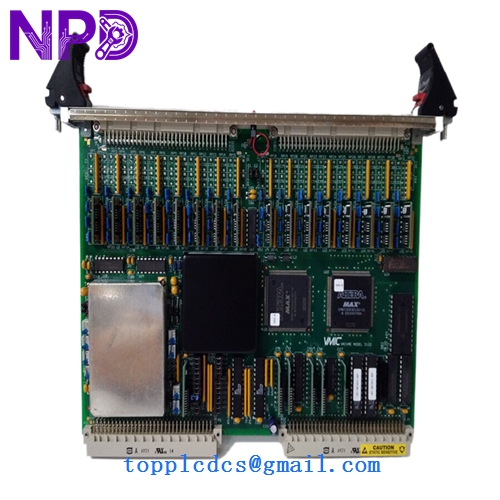
GE VMIVME-3122
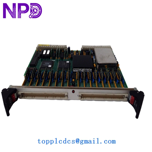
GE VMIVME-3122
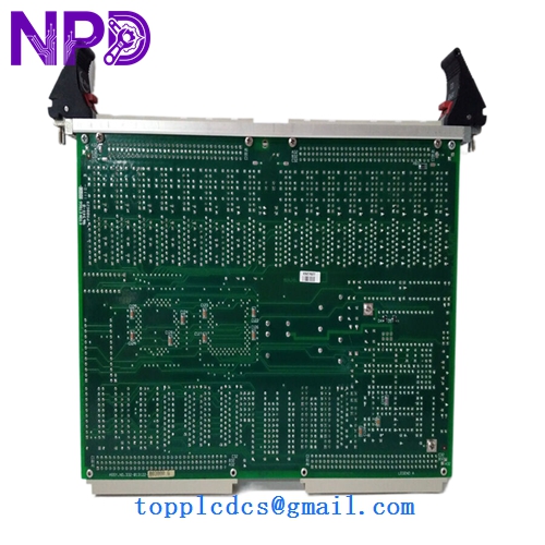
GE VMIVME-3122
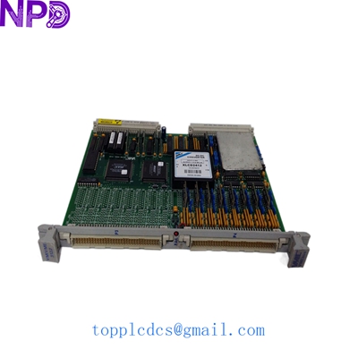
GE VMIVME-3122-210 VMIVME3122
Installation & Configuration Guide
Phase 1: Preparation (Pre-Installation)
Estimated time: 15 minutes
⚠️ Safety Warning:
- Power Down: Ensure the VME chassis is completely powered off before inserting or removing the board.
- Backplane Pins: VME backplanes have many fragile pins. Align the board carefully with the guide rails to prevent “pin pushing.”
- ESD Precautions: This board contains sensitive CMOS components. Use a grounded wrist strap.
Required Tools:
- VME Chassis with an available 6U slot.
- Slot-head or Phillips screwdriver for securing the front panel.
- Documentation for your VME host (to assign the correct base address).
Phase 2: Hardware Address Setting (Jumpers)
Estimated time: 10 minutes
Step 1: Base Address Selection Before insertion, you must set the VMEbus base address using the onboard DIP switches or jumpers (typically labeled JP1/JP2).
- Match these settings to your software’s memory map.
- If replacing an old unit, mirror the switch positions exactly.
Step 2: Interrupt Level Configure the VME interrupt level (IRQ1-IRQ7) based on your system’s priority requirements.
Phase 3: Module Insertion & Integration
Estimated time: 20 minutes
- Insertion: Slide the VMIVME-3122 into the chassis. Press the ejector handles inward until the board is fully seated in the P1/P2 connectors.
- Wiring: Connect your analog signals to the front-panel P3/P4 connectors.
- For Differential inputs, ensure pairs are twisted to minimize noise.
- For Single-ended inputs, ensure a common ground reference.
- Power Up: Turn on the chassis. The “Run” or “Health” LED on the board should illuminate.
- Software Validation:
- Perform a “VME Probe” to see if the host recognizes the board at the assigned address.
- Run a test scan on Channel 0 using a known DC voltage source to verify 16-bit accuracy.
Customer Cases & Industry Applications
Case 1: Aerospace Test Stand Calibration A major aerospace contractor used the VMIVME-3122 for high-fidelity data acquisition during jet engine testing. The 16-bit resolution was critical for detecting minute pressure fluctuations. When a board failed due to a laboratory power surge, we provided a New Surplus unit overnight. The contractor was able to resume testing within 24 hours, maintaining their strict project timeline for the Department of Defense.
Case 2: Legacy Industrial Control System Maintenance A large steel mill used a VME-based control system for its rolling mill. The system relied on the VMIVME-3122 to monitor feedback from hundreds of sensors. As GE Fanuc moved these boards to “End of Life,” the mill struggled to find replacements. By purchasing two New Surplus units from us, they extended the life of their existing multi-million dollar control system by another 10 years, avoiding the massive cost of a full system migration.
Frequently Asked Questions (FAQ)
Q: Can I mix Differential and Single-ended inputs on the same board? A: Typically, the board is configured for either 64 single-ended or 32 differential channels via hardware jumpers. In my experience, it is best to stick to one mode per board to ensure signal integrity and simplify software scaling.
Q: Does the VMIVME-3122 require periodic calibration? A: While it has a high-stability onboard reference, industrial standards usually recommend a yearly calibration check. The board supports auto-calibration via software commands, which helps maintain the ±0.005% accuracy without manual adjustment.
Q: Is the VMIVME-3122 compatible with all VME chassis? A: It is a standard 6U VMEbus module. It is compatible with VME64 and legacy VMEbus backplanes. Just ensure your chassis power supply can handle the +5V and ±12V draw required by the high-precision analog circuitry.
Q: How do I know if I have the -000 or -100 version? A: Check the side label. The suffix usually denotes factory-set gain ranges or specific filter frequencies. If you are unsure, provide us with the full part number and we can verify the configuration for you.
Q: What is “New Surplus” in the context of VME boards? A: These boards were purchased as spares for large projects but never used. They are “New-in-Box,” meaning the gold fingers on the VME connectors are pristine and the board has never been exposed to the heat and dust of an active industrial environment. This is the highest quality available for legacy VME hardware.