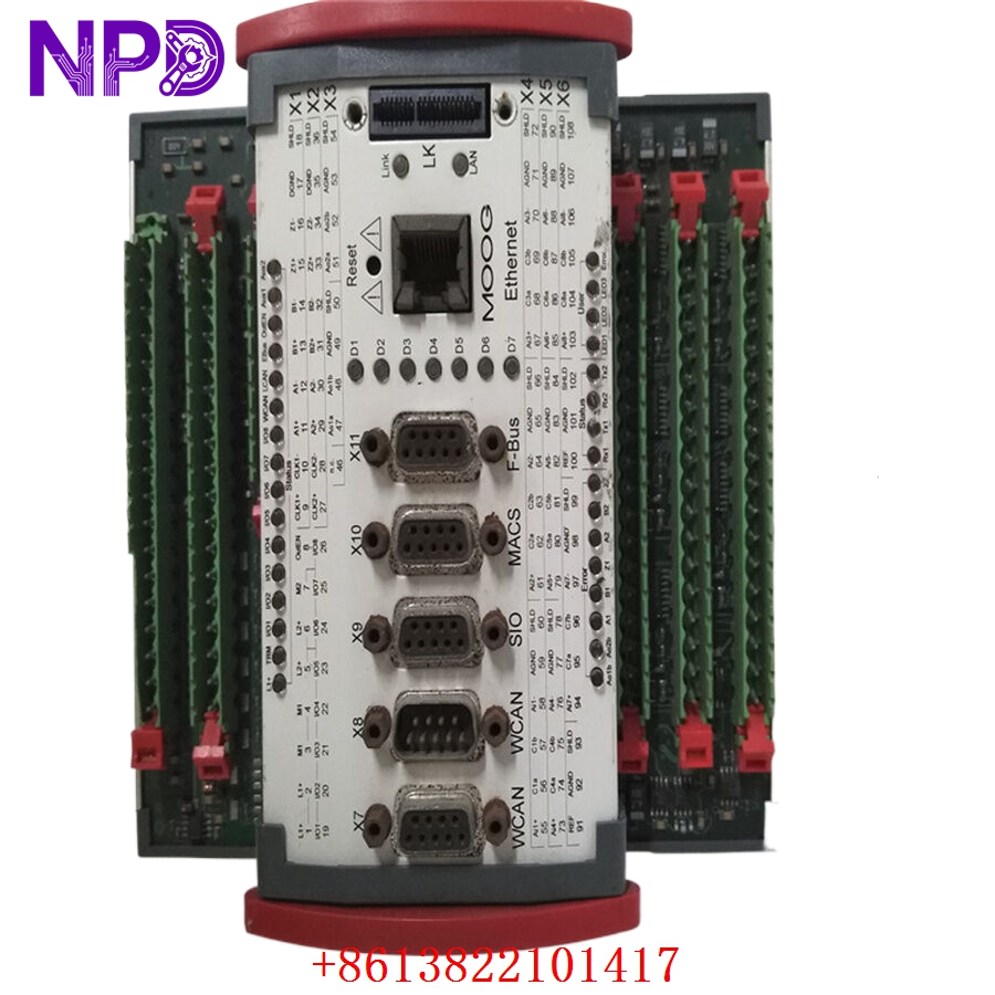
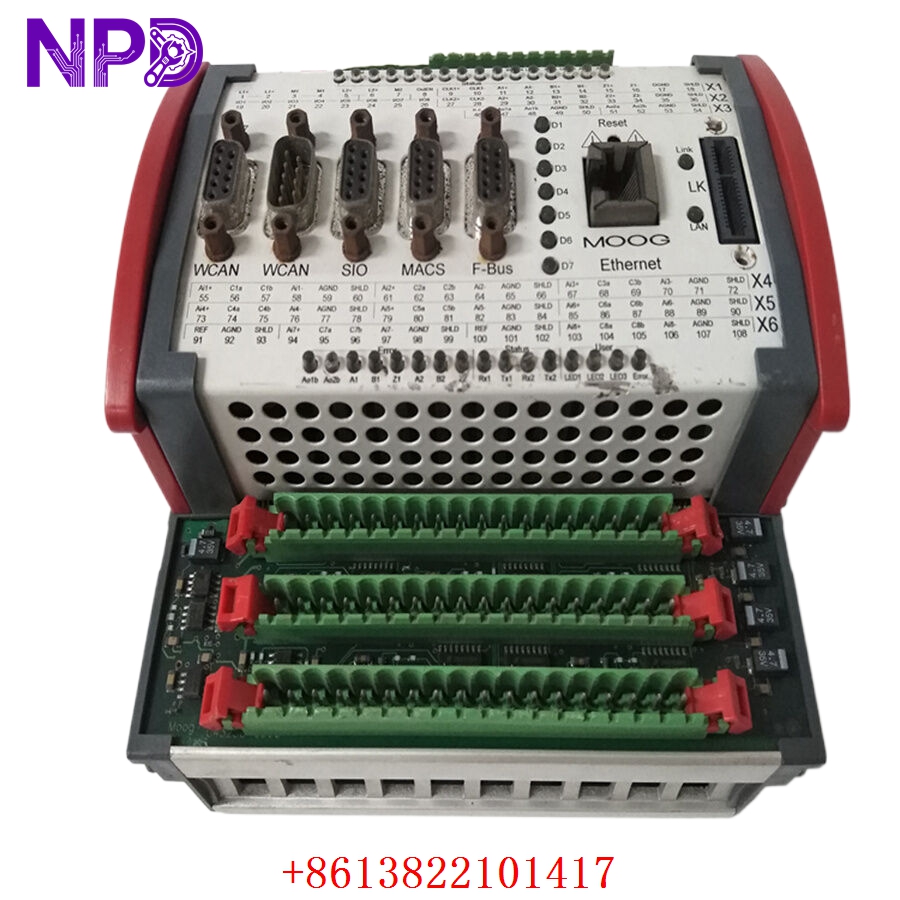
Description
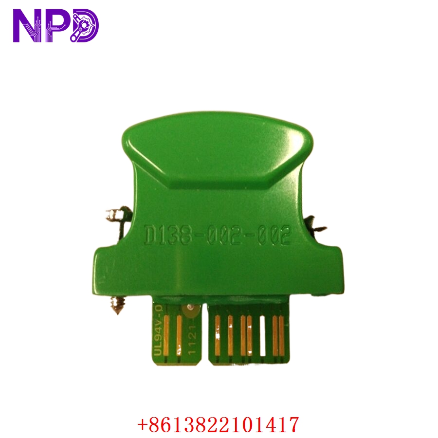
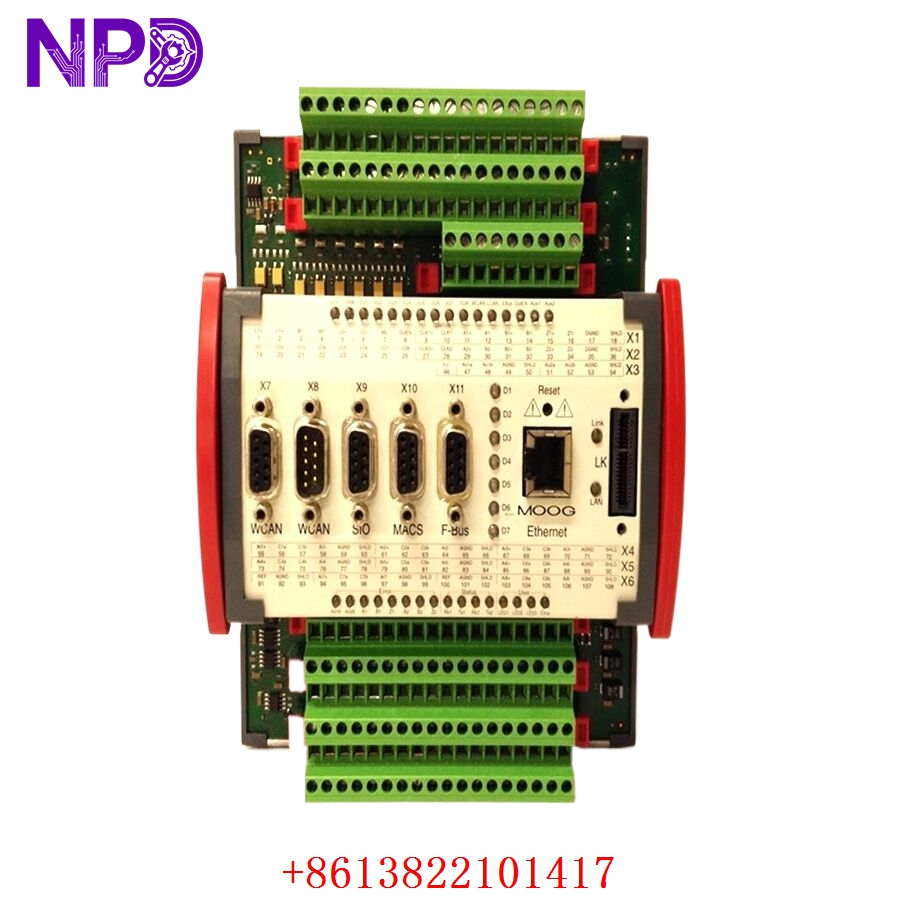
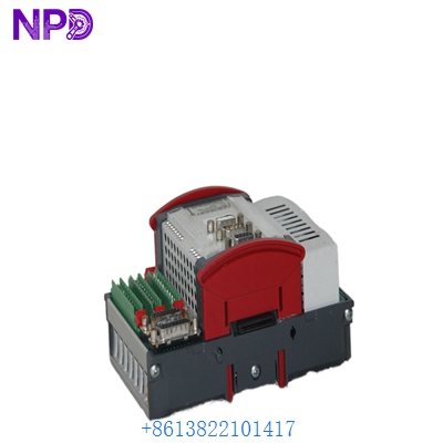
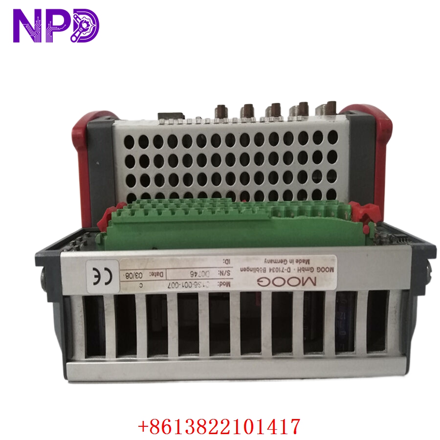
- Model: MOOG D136-001-007
- Brand: MOOG (Germany / USA)
- Series: MSC I (Moog Motion Control System I) Product Family
- Core Function: High-performance, multi-channel programmable servo controller with integrated PLC logic, purpose-built for high-speed closed-loop control of 1 to 2 hydraulic servo-actuators or proportional valves, New Surplus / Clean Used condition
- Type: Two-Axis Closed-Loop Digital Motion Controller
- Key Specs: 32-bit PowerPC RISC Processor (with Floating-Point Unit), 400 \mus deterministic loop cycle time, 8x 16-bit configurable analog inputs, 2x 16-bit analog outputs, 2x EIA-422 configurable sensor interfaces (SSI/Incremental)
- Processing Core: 32-bit PowerPC processor with RISC architecture and an integrated hardware floating-point calculation unit
- System Flash Memory: 4 MB onboard EEPROM capacity with a typical data retention profile of 10 years
- Execution Performance: 400 \mus fixed execution cycle time for simultaneous 2-axis independent loop processing
- Analog Inputs: 8 channels, non-isolated, 16-bit analog-to-digital resolution. Independently software-configurable via MACS for \pm10 V, \pm10 mA, or 4-20 mA ranges. Continuous overvoltage protection up to \pm36 V
- Analog Outputs: 2 channels, 16-bit digital-to-analog resolution. Native voltage output range of \pm10 V; software-configurable for \pm10 mA, \pm50 mA, or 4-20 mA standard industrial current drives
- Reference Voltage Source: Integrated +10 V DC output (5 mA maximum current capacity), protected against short-circuits and lines up to \pm36 V
- Position Feedback Sensor Ports: 2 independent sensor channels compliant with EIA-422 differential line standards. Features line fault monitoring
- Transducer Configuration Profiles:
- Incremental Encoder: Up to 8 MHz maximum pulse frequency with 4-edge evaluation tracking
- SSI (Synchronous Serial Interface): Supports Gray code or binary formatting, selectable length from 8 to 32 bits, transmission frequencies ranging from 78 kHz up to 5 MHz
- System Input Power: 24 V DC (operational window: 18 V to 36 V DC), compliant with SELV standards according to EN 60950-1
- Current Consumption Parameters: 0.5 A base no-load current; up to 2.0 A maximum load current draw
- Electrical Potential Isolation: Independent galvanic isolation barriers separating module logic circuits, 24 V input rails, digital I/O lines, and Ethernet networks
- Programming Environment: Configured and commissioned via Moog Axis Control Software (MACS) using standard IEC 61131-3 languages
- Mechanical Design & Housing: Compact DIN-rail mount chassis with IP20 protection rating (requires enclosure installation)
- Physical Envelope Constraints: 160 mm W x 170 mm D x 85.5 mm H
- Net Hardware Mass: 1.26 kg
MOOG D136-001-007
MOOG D136-001-007
MOOG D136-001-007
Application Scenarios & Pain Points
In specialized metallurgy plants, heavy rolling mills, and power generation stations, the MOOG D136-001-007 controller serves as the primary intelligence coordinating hydraulic positioning loops. Because hydraulic fluids operate under extreme pressures, even tiny control command lags can lead to massive physical hammering, valve shuttering, or catastrophic actuator over-travel.
When the analog processing chips or the internal PowerPC core on an older D136 module degrade under continuous thermal stress, the controller may drop its positioning signals, loop tracking fails, and the supervisor system trips the entire line. Locating an exact matching replacement running the proper baseline hardware revision is essential: unexpected version changes can cause communication dropouts with the field linear transducers (SSI/Incremental) or throw scaling errors that complicate mill re-commissioning.
Typical Application Scenarios
- Metallurgical Facilities – Steel Mill Roll Gap Control
Directs high-speed hydraulic screw-down cylinders to maintain micrometer-level precision across hot or cold rolling mill matrices.
- Power Generation – Main Steam Turbine Governor Control
Manages high-fidelity loop positioning for electro-hydraulic actuator assemblies controlling steam throttle and intercept valves.
- Plastic Processing – Injection Molding Clamping Assemblies
Controls multi-stage proportional directional valves to govern clamp velocity mapping, precise mold protection zones, and core pulling cycles.
Real-World Field Case: Fixing an Intermittent Hydraulic Axis Shutdown
Background: A high-output hot-strip rolling facility in northern China was experiencing intermittent axis tracking faults on its secondary roughing stand. The controller rack utilized a dedicated MOOG MSC I architecture for hydraulic gauge adjustment.
The Problem: During peak compression strokes, Axis 2 would suddenly drop out, triggering a “Position Transducer Line Fault / Timeout” warning on the engineering terminal. When this happened, the gauge control loop defaulted, forcing a safety lift sequence that ruined the sheet metal strip in process. Technicians discovered that the differential EIA-422 input receiver chip inside the older D136-001-007 controller was failing whenever heat in the non-vented local cabinet exceeded 55 °C, dropping the SSI position clock.
The Solution: The maintenance superintendent contacted our logistics team. We pulled an exact matching D136-001-007 motion controller from our warehouse inventory, executed full 16-bit analog loop sweeps across all 8 inputs on our test fixture, validated the SSI differential transceiver pathways at 2 MHz, and dispatched the module via premium air-express courier.
The Result:
- Delivery Timeline: The hardware arrived at the plant’s production office in under 18 hours.
- Implementation: The mill’s controls team loaded the existing MACS application project file onto the new controller, locked it onto the DIN rail, and reconnected the I/O terminals.
- System Performance: The axis stabilized immediately. The replacement unit handled the high-frequency calculation demands flawlessly, maintaining zero-drift feedback through subsequent high-heat operational runs.
Compatible Replacement Models
When replacing high-speed hydraulic loop controllers, pay close attention to the interface type, as variations alter the pin assignments and network topology.
- MOOG D136-001-007 (Exact Specification Match) → Direct Drop-in Replacement
- Configuration: Standard MSC I base unit with 8 analog inputs, 2 analog outputs, and 2 position sensor channels.
- Action: Move the terminal clusters and communications links over point-to-point. Run your original software image via MACS.
- MOOG MSC II Series Controllers (e.g., D136 Embedded Upgrades / Next-Gen MSC II) → System Re-engineering Required
- Differences: Next-generation MSC II controllers expand standard capacity up to 4 position sensor interfaces and integrate additional hardware fieldbus channels (such as native EtherCAT or Profibus-DP slave interfaces).
- Recommendation: Do not attempt to mount an MSC II module as an emergency drop-in replacement for a D136-001-007 unless you are prepared to adjust your field network topologies and rewrite hardware allocation parameters inside an updated version of the MACS programming engine.
Troubleshooting Quick Reference
Use this specialized guide to isolate issues with the D136 module when investigating hydraulic loop errors on the plant floor.
| Diagnostic Observation | Probable Root Cause | Module Component Relevancy | Field Diagnostic Test Steps | Remediation Protocol |
| MACS Software flags an “SSI Sensor Line Fault” | Broken differential pair wiring or a failed EIA-422 receiver on the board | ✅ High | Check line voltages across the differential clock and data line pins with an oscilloscope. Check for a 5V base profile. | If the sensor functions on another channel but fails on this specific port with clean signals arriving, the internal differential receiver chip is damaged. Replace the D136 controller. |
| Analog output fails to drive the servo valve coil | Blown analog output path or field coil open-circuit | ⚠️ Medium | Disconnect the valve cable. Force a 5V output via MACS and measure the raw voltage directly at the module output terminals. | If the terminal reads 5V when unloaded but drops to 0V when connected, check the valve coil impedance for an internal short. If the terminal reads 0V while forced, replace the module. |
| Cyclic “Watchdog Reset” errors in the system log | Corrupt application logic partition or internal CPU fault | ✅ High | Clear the internal user memory sectors and download a verified, unedited backup version of the MACS runtime code. | If the PowerPC chip continues to cycle and reset when running standard baseline code, its internal RAM or power monitor is compromised. Replace the unit. |
| High signal jitter on analog feedback lines | Induced electromagnetic noise on unshielded lines | ⚠️ Medium | Verify that all analog input lines utilize twisted-pair shielding grounded exclusively at the control panel side. | Ensure the D136 module’s DIN-rail ground clip makes clean metal-to-metal contact with an unpainted, properly grounded backing plate. |
❗ HYDRAULIC SAFETY WARNING: Before disconnecting the terminal connectors or replacing a running D136-001-007 module, verify that the hydraulic power unit (HPU) is fully de-energized and system accumulator pressures have been safely vented. Swapping an active loop controller while lines are under pressure can cause the proportional valve spool to shift unexpectedly, leading to sudden, uncommanded cylinder movement.
If your plant floor technicians need to verify our current inventory’s exact firmware compatibility profiles or require a detailed walkthrough of our automated validation processes before placing a shipment block, connect with our support desk today. We will deliver the data you need within two hours.