Description
Product Core Brief
| Attribute | Detailed Information |
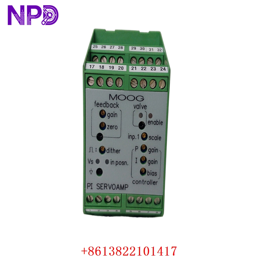
| Model | MOOG D136-001-001 |
| Brand | MOOG Inc. |
| Series | D136 Servo Control / Interface Series |
| Core Function | Servo loop control and transducer signal conditioning |
| Product Type | Servo Controller / Interface Module |
| Key Specs | ±10 V Input/Output / High-bandwidth Response / DIN Rail Mount |
Key Technical Specifications
- Supply Voltage: 24 V DC (typically ±15 V DC internal regulation)
- Command Input: ±10 V Differential or Single-ended
- Output Signal: ±10 V (Standard servo valve drive signal)
- Frequency Response: High bandwidth (>1 kHz typical for control electronics)
- Transducer Interface: Supports LVDT (Linear Variable Differential Transformer) or Potentiometer feedback
- Adjustments: On-board potentiometers for Gain, Zero Offset, and Dither
- Mounting: Standard DIN Rail or specialized Moog rack-mount frames
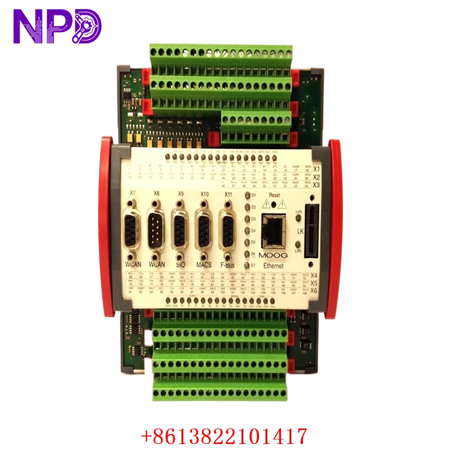
- Connectors: Screw terminals or high-density D-sub (depending on sub-revision)
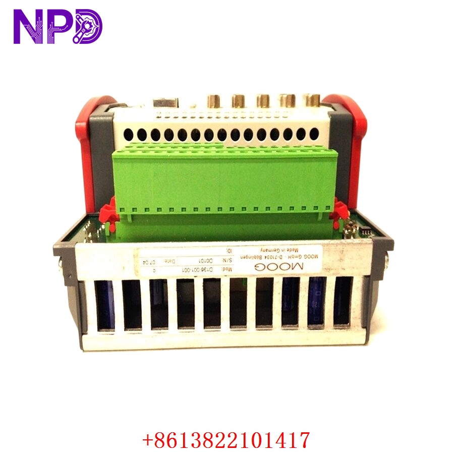
MOOG D136-001-001
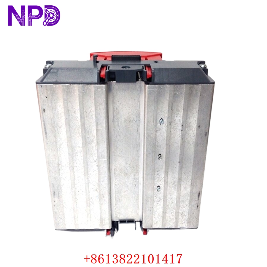
MOOG D136-001-001
MOOG D136-001-001
Application Scenarios & Pain Points
The MOOG D136-001-001 is a precision instrument designed to sit between your PLC and a high-performance servo valve. While the PLC makes the “decisions,” the D136 does the heavy lifting of managing the sub-millisecond feedback loop required for ultra-precise hydraulic or electric motion.
The Engineering Challenge:
The biggest headache with Moog electronics is tuning. Unlike a standard digital PLC module, the D136 often relies on analog balancing. If this module fails, you don’t just lose a signal—you lose the stability of the entire mechanical axis. Without the D136, a hydraulic ram might “hunt” (oscillate) or slam into its end-stops. Finding a replacement that matches the original series’ response time is critical to avoid re-tuning the entire hydraulic PID loop, which can take days of trial and error.
Typical Application Scenarios:
- Injection Molding – Clamping Control
Managing the high-speed, high-force transition of the mold clamp with sub-millimeter precision.
- Steel Mills – Gap Control
Controlling the hydraulic cylinders that set the gap in rolling mills, requiring instantaneous response to pressure changes.
- Power Generation – Steam Turbine Valve Actuation
Interfacing with Moog servo valves to modulate steam flow for precise frequency control.
- Testing Rigs – Aerospace Simulators
Providing the high-fidelity signal conditioning needed for flight surface simulation actuators.
Case Study: The “Shaking” Press at an Automotive Plant
Background: A Tier-1 auto parts supplier used a Moog-controlled hydraulic press for forming chassis components. The system used a D136-001-001 to close the position loop.
Problem: The press started vibrating violently at the end of its stroke. The maintenance team suspected the servo valve, but testing showed the valve was fine. The issue was actually a drifting feedback capacitor on the D136-001-001 card, which was introducing phase lag and causing the loop to become unstable.
Solution: We supplied a new surplus D136-001-001. Because this was an exact series match, the technician was able to simply copy the potentiometer turns (Gain and Offset) from the old card to the new one.
Result:
- Stability Restored: The vibration stopped immediately upon installation.
- Production Saved: The line was back to full speed in under 4 hours, avoiding an expensive overhaul of the hydraulic cylinders.
Compatible Replacement Models
Moog parts are highly specific; always check the dash numbers.
| Original Model | Alternative Model | Compatibility Level | Notes |
| D136-001-001 | D136-001-002 | ⚠️ Software Compatible | May have different dither frequency settings. |
| D136-001-001 | D136-xxx (Custom) | ❌ Incompatible | “xxx” versions are often factory-set for specific valves. |
| D136-001-001 | Moog MSC Series | ❌ Hardware Modification | The MSC is the modern digital successor; requires new software. |
Troubleshooting Quick Reference
| Symptom | Possible Cause | Relevance | Quick Check | Action |
| Axis “Drifts” at Null | Zero Offset Drift | ✅ High | Measure the output voltage with a 0V command input. | Adjust “Zero” pot; if it won’t balance, the module is failing. |
| Valve Doesn’t Move | Command Loss / Power | ⚠️ Medium | Verify ±15 V / 24 V supply at the module pins. | If power is OK but no output, the driver stage is blown. |
| Erratic Axis “Chatter” | Dither Set Too High | ✅ High | Check the Dither frequency and amplitude pots. | Reduce dither; if chatter persists, the filter stage is failed. |
| Full-Scale Saturation | Feedback Open-Loop | ⚠️ Medium | Check LVDT/Potentiometer wiring back to the D136. | If wiring is solid, the feedback conditioning circuit is dead. |
Field Engineer’s Insight:
When you install a new D136-001-001, do not assume the factory potentiometer settings are right for your machine. Every servo valve has a slightly different “null” point. Start with the Gain pot at a lower setting than the old card, then gradually bring it up until the axis is snappy but doesn’t oscillate.
❗ Warning: Moog cards are susceptible to electrical noise. Ensure your shield is tied to a clean “instrument earth” and not the noisy motor ground. I’ve seen these modules fail prematurely because of “ground bounce” in poorly bonded cabinets.
Need the pin-out diagram to verify your LVDT connections? Let me know, and I’ll send you the terminal map for the 001-001 revision.