
Description
Product Core Brief
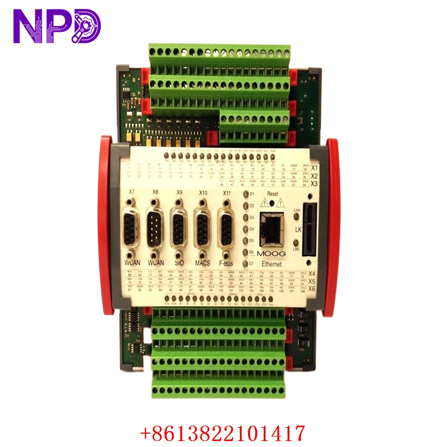
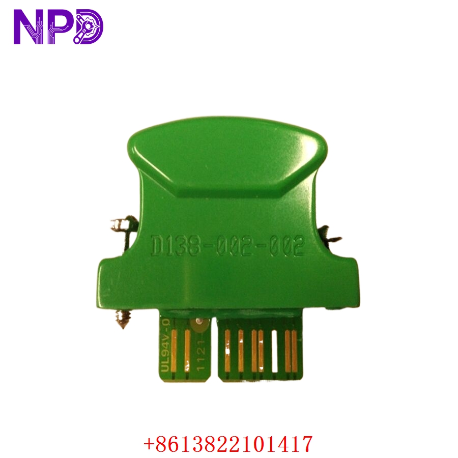
- Model: D138-002-002
- Brand: MOOG (USA/Germany)
- Series: D138 Series Motion Control
- Core Function: High-speed, programmable control of servo valves and brushless servo motors
- Type: Programmable Motion Controller / Servo Interface
- Key Specs: High-resolution analog I/O CANbus/Serial communication Modular DIN-rail design\
Key Technical Specifications
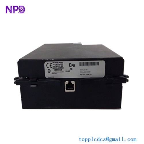
- Processor: 32-Bit High-Performance Microcontroller
- Input Voltage: 24 V DC (18 to 32 V DC)
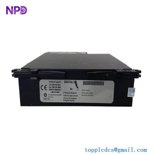
- Analog Inputs: Multiple high-resolution (12-bit to 16-bit) configurable for ±10V or 4-20mA
- Analog Outputs: Dedicated high-speed outputs for Servo Valve pilot control
- Digital I/O: Opto-isolated 24V Logic inputs and outputs
- Communication: CANopen interface (for multi-axis synchronization) and RS-232/485 for configuration
- Control Loop Time: Typical < 1 ms (Task-dependent)
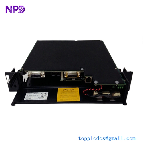
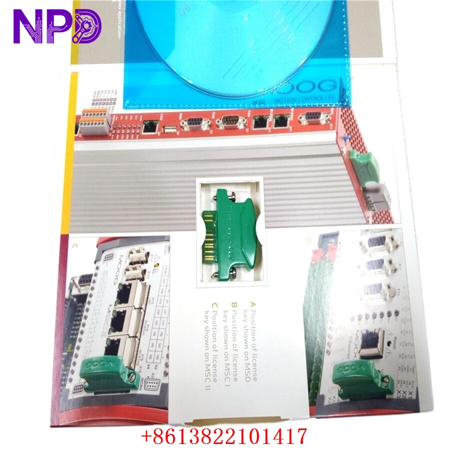
- Mounting: Standard 35mm DIN Rail
- Indicators: Diagnostic LEDs for Power, Status, and Fieldbus Activity
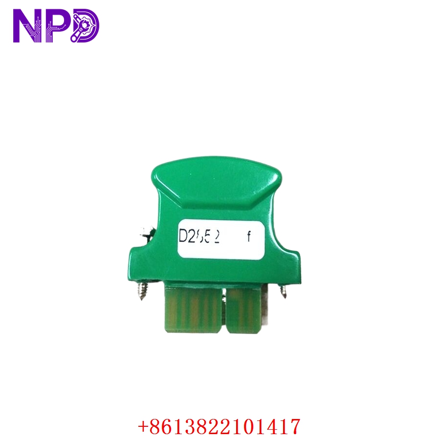
MOOG D138-002-002
MOOG D138-002-002
MOOG D138-002-002
Installation & Configuration Guide
Phase 1: Pre-Installation (Estimated time: 15 minutes)
⚠️ Safety Protocol:
- Hydraulic Safety: If this controller is linked to a hydraulic servo valve, ensure the hydraulic system is depressurized. Unexpected valve actuation can cause sudden, violent machinery movement.
- Ensure your 24V power supply is “clean” (low ripple). Moog controllers are high-precision instruments and sensitive to electrical noise.
- Verify the Firmware Version of your existing unit. Programmable controllers often carry custom application code specific to the machine.
Phase 2: Removal (Estimated time: 10 minutes)
- Backup: If the old unit is still responsive, use the Moog configuration software to upload the existing parameter set.
- Wiring: Carefully disconnect the Phoenix-style terminal blocks. I recommend labeling the transducer and valve signal wires specifically, as they often use similar colors.
- Grounding: Disconnect the shield/grounding wires last.
Phase 3: Configuration (Estimated time: 30 minutes)
- Software: You will likely need the Moog MACS (Moog Axis Control Software) or a similar proprietary tool depending on your machine’s integration.
- Parameters: Load the machine-specific configuration file (.macs or .set).
- Nulling: In servo valve applications, you may need to perform a “Mechanical Null” or “Electronic Null” to ensure the valve is centered when the command is at zero.
Phase 4: Commissioning (Estimated time: 30 minutes)
- Dry Run: Test the digital I/O (Enable/Reset) without hydraulic power or motor high-voltage enabled.
- Loop Check: Monitor the feedback signal from the LVDT or encoder to ensure it matches the physical position.
- Tuning: If the machine response is sluggish or oscillates, fine-tune the PID (Proportional, Integral, Derivative) gains. Caution: Start with very low gains to avoid instability.
Customer Cases & Industry Applications
Case 1: Plastic Injection Molding Clamp Control
Situation: A high-end plastic injection molding machine in Germany had a D138-002-002 fail. The clamp movement became erratic, causing the machine to trip on a “Position Deviation” fault. Task: The manufacturer was quoting a 16-week lead time for a replacement. Every day of downtime was costing the customer €4,000. Action: We supplied a New Surplus D138-002-002. I helped their maintenance team understand the LED error codes, which pointed to a failed analog input channel on the original unit. Result: The customer received the part in 3 days. After loading their original parameters, the machine returned to micron-level precision, and production resumed immediately.
Case 2: Aerospace Test Rig Actuation
Situation: An aerospace testing facility was using Moog controllers to simulate flight loads on wing flaps. A power surge damaged the D138 controller in the main control cabinet. Task: The facility required a “New Surplus” part with documented serial numbers for their quality control logs. They could not use a “used” part for flight-safety related testing. Action: We provided a unit in its original factory packaging. We verified the serial number and manufacturing date to meet their traceability requirements. Result: The test rig was back online within the week. The “New Surplus” status satisfied their rigorous internal audit and safety standards.
Frequently Asked Questions (FAQ)
Q: Can I use a D138-002-001 to replace a D138-002-002? A: Generally, no. The trailing digits (-002-002) usually denote specific hardware revisions or pre-loaded software/interface configurations. While they look identical, the internal memory or I/O mapping may differ. Always match the full part number for a “Plug and Play” experience.
Q: Why does the “Status” LED flash red upon power-up? A: A flashing red LED on a Moog controller usually indicates a “System Fault” or “Missing Parameter Set.” It means the hardware is healthy, but it doesn’t have the instructions (the program) to start operating. You need to download the configuration via the serial port.
Q: Is it okay to buy “New Surplus” if the part is several years old? A: Yes. Moog designs their industrial controllers for 20+ year lifespans. As long as the unit has been stored in a clean, dry, anti-static environment (which ours are), the internal components like capacitors will remain in excellent condition.
Q: Does this unit include the LVDT feedback board? A: The D138-002-002 is a modular controller. It typically includes the standard analog/digital interface. If your application requires a specific high-frequency LVDT interface, verify that the daughter-board is installed or that you can transfer it from your old unit.
Q: How do I get the software for this? A: Moog software is usually provided with the machine or by Moog directly. If you are a technical distributor or an end-user, we can often assist you in identifying the correct version of MACS or the required .DLL files for your system.