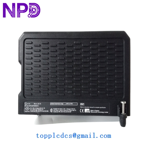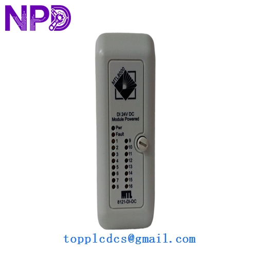

Description
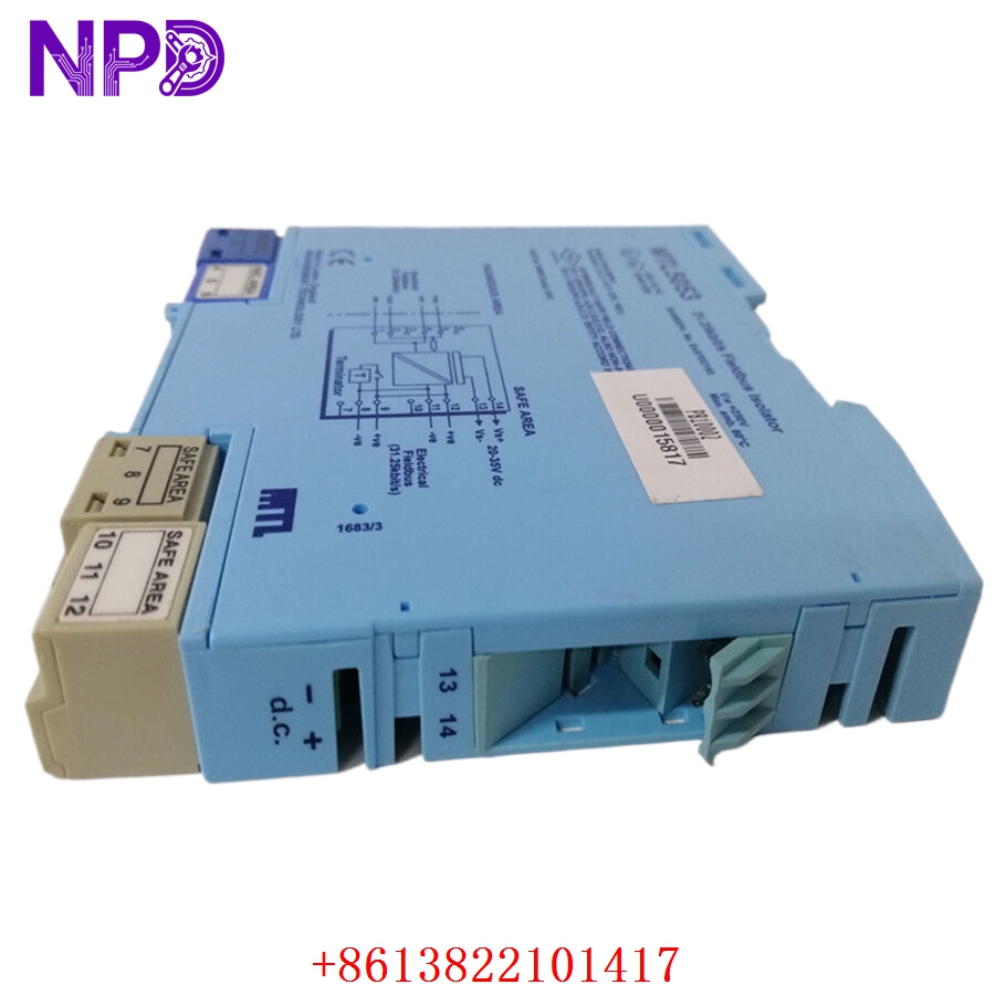
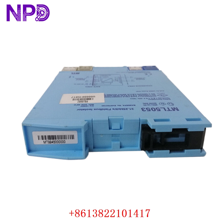
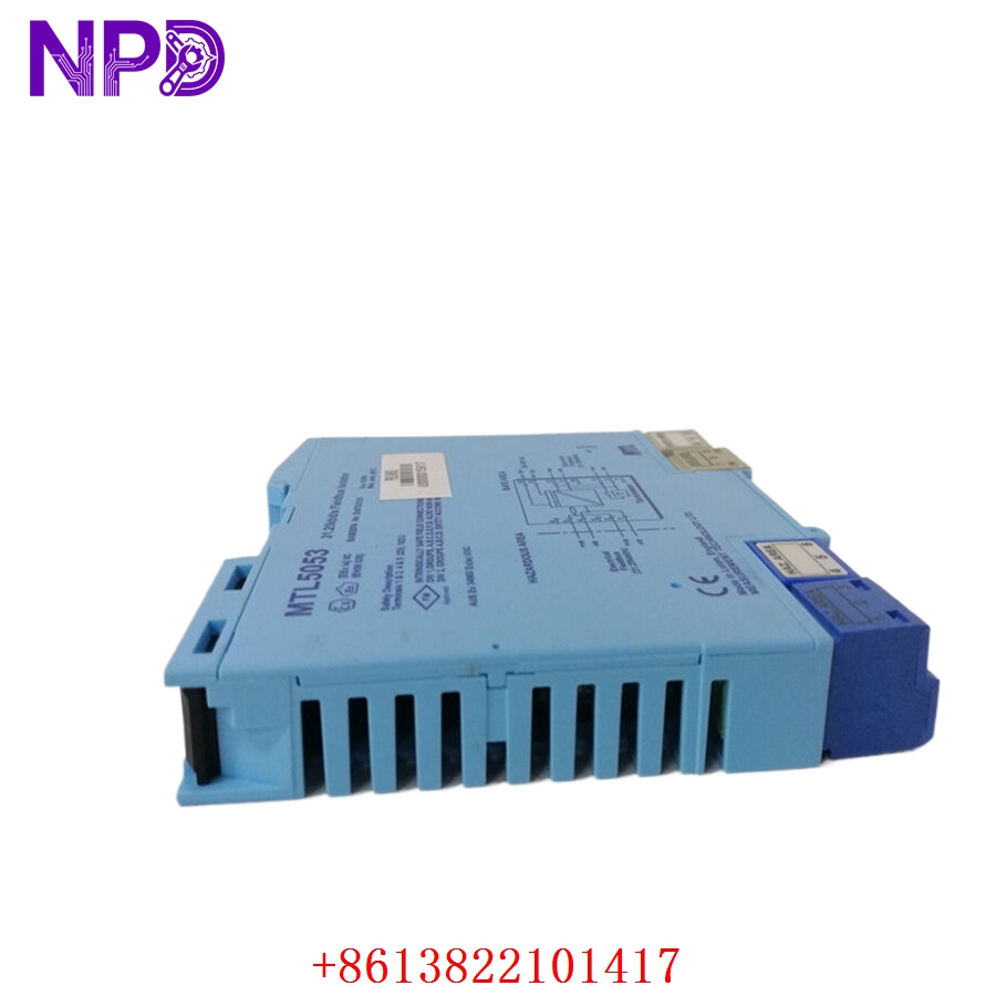
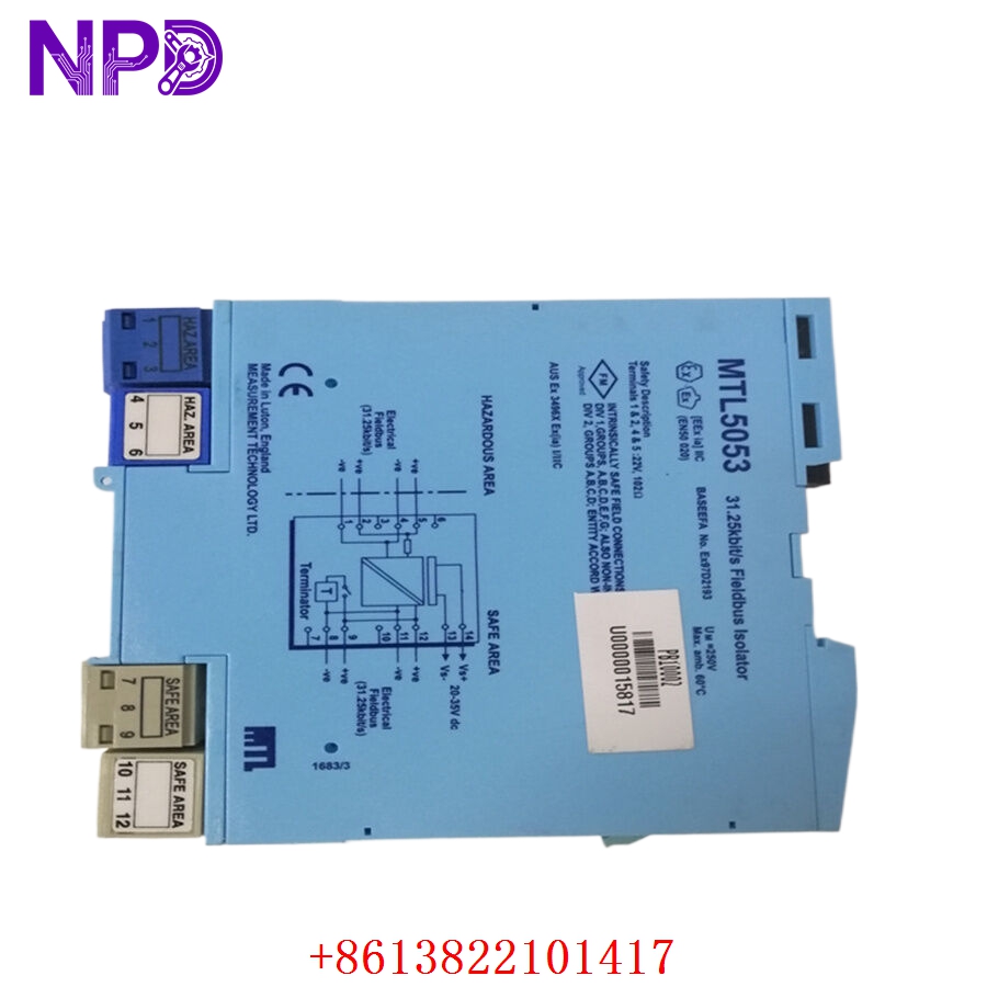
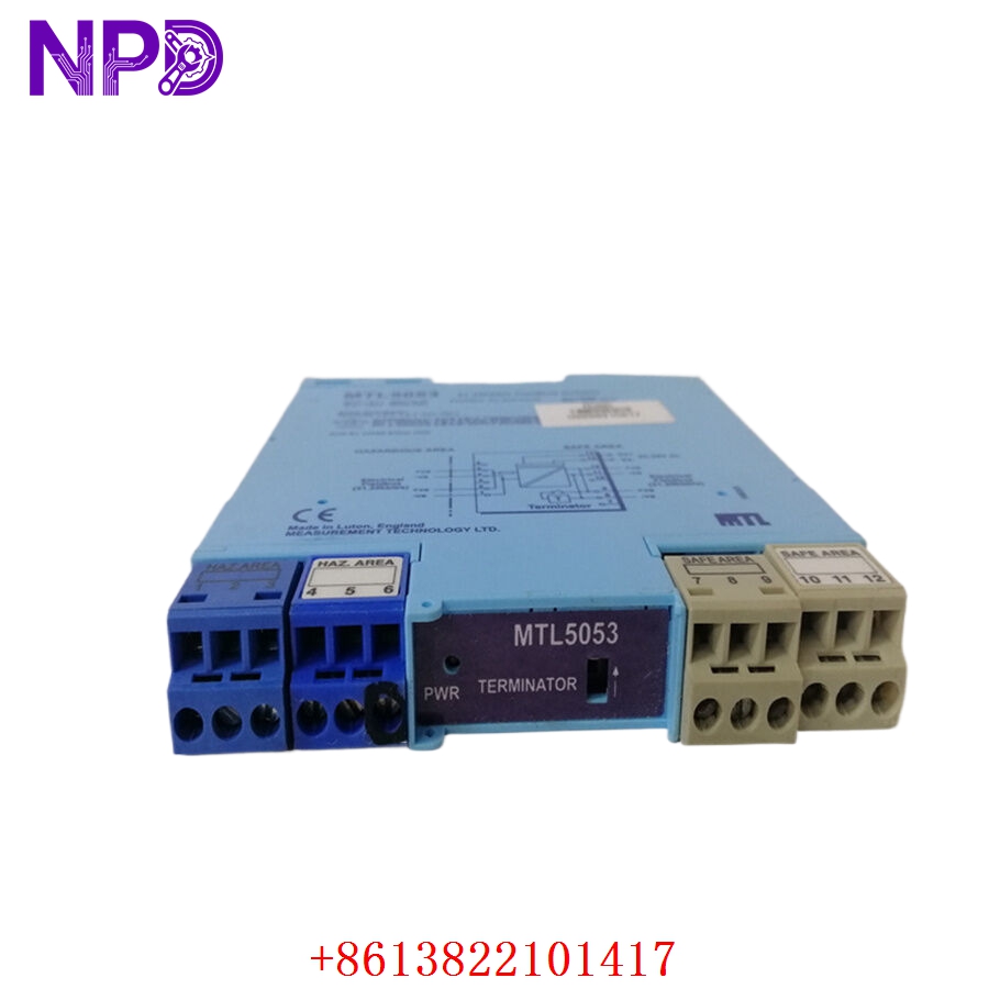
- Model: MTL MTL5053
- Brand: MTL (Eaton / Crouse-Hinds)
- Series: MTL5000 Series
- Core Function: Transfers pulse/frequency signals from hazardous areas to safe-area control systems (e.g., PLCs, counters) while providing galvanic isolation.
- Product Type: Galvanic Isolated Pulse Isolator
- Key Specs: Supports proximity switches or switch inputs, IS certified, dual-channel option
- Hazardous Area Input: Suitable for switch or proximity sensor (NAMUR standard)
- Safe Area Output: Open collector transistor or relay (dependent on specific configuration)
- Isolation: Galvanic isolation between input, output, and power supply
- Safety Rating: Intrinsically Safe (IS) for hazardous area applications
- Frequency Range: High-speed pulse capability for flow meters/tachometers
- Power Supply: 20–35 V DC
- Mounting: DIN rail mounting
- Certification: ATEX/IECEx compliant for zones 0, 1, and 2
MTL MTL5053
MTL MTL5053
MTL MTL5053
MTL MTL5053
Application Scenarios & Engineering Pain Points
The MTL5053 is essential for industrial environments where explosive atmospheres (like gas or dust) are present. The most common engineering challenge is “Loop Integrity.” Because the barrier is designed to limit the energy sent into the hazardous area, engineers often struggle with “signal attenuation.” If the cabling from the field to the barrier is too long or has high resistance, the proximity sensor may fail to trigger the input threshold on the barrier, leading to “lost pulses” in flow metering or speed monitoring applications.
Typical Application Scenarios:
- Oil & Gas – Tank Farm Flow Monitoring Transfers pulses from turbine flow meters located in high-risk zones to the safe-area PLC.
- Chemical Processing – Pump Speed Control Provides safe isolation for tachometer signals from motors operating in volatile vapor zones.
- Refinery – Safety Instrumented Systems (SIS) Inputs signals for emergency shutdown logic from field-mounted safety switches.
Case Study: Pulse Loss in Hazardous Gas Zone A refinery noted that their flow meters were under-reporting throughput. After verifying the field sensors were working, the engineering team realized the MTL5053 was receiving a degraded signal due to excessive cable length (over 300 meters) from the field. By switching to a lower-capacitance shielded cable and ensuring the NAMUR sensor input voltage was correctly stabilized, they restored the pulse signal integrity, eliminating the measurement discrepancy.
Troubleshooting Quick Reference
Don’t assume the barrier is faulty; most issues with pulse barriers are related to field cabling or sensor power.
| Failure Symptom | Possible Cause | Quick Check Method | Recommended Action |
|---|---|---|---|
| No Pulse Output | Sensor/Switch Fault | Check input voltage at barrier (NAMUR) | Verify sensor connection at field |
| “Safe” LED Dark | Power Failure | Measure 24 V DC supply at terminals | Check fuse and power distribution |
| Signal “Jitter” | Ground Interference | Check shield termination/continuity | Ensure barrier is correctly earthed |
| Input Fails to Trigger | Line Impedance/Capacitance | Verify cable length vs. spec | Shorten cable or use low-cap wire |
Engineer’s Note: ❗ Crucial Advice: Always keep the hazardous area wiring separated. Even inside the control cabinet, you must maintain a physical distance (usually 50 mm) between the “Intrinsically Safe” wiring (the side connected to the hazard) and the standard “Non-IS” control wiring. If these wires cross or run in the same cable tray, you violate the IS certification and create a massive safety risk.