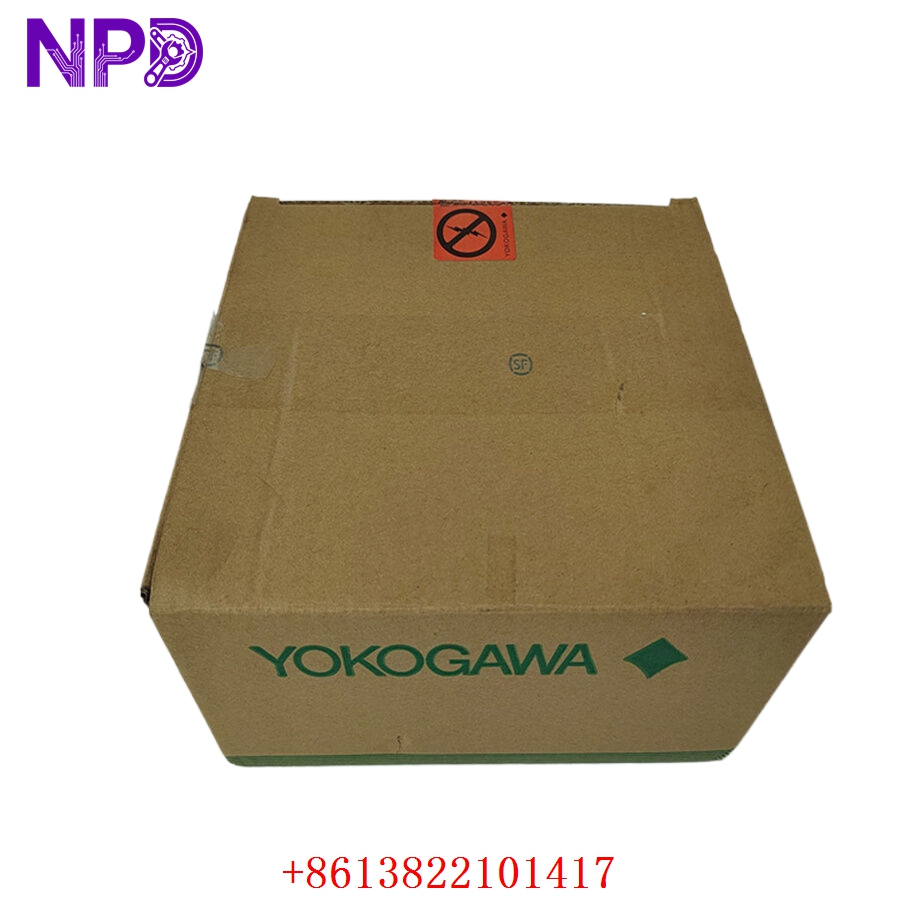

Description
The Yokogawa ANB10D-410 S2 is a high-reliability node interface and base unit engineered specifically for the Yokogawa CENTUM VP distributed control system (DCS). It functions as a foundational expansion chassis that houses power supply modules, communication cards, and I/O module slots, enabling seamless signal acquisition and distribution across remote or local control nodes. Built for demanding industrial process automation environments, it ensures high availability, robust backplane communication, and dependable system expansion.

📊 Product Datasheet
| Parameter | Value |
| Brand | Yokogawa |
| Model / Suffix | ANB10D-410 S2 |
| Series | CENTUM VP ESB Bus Node Series |
| Product Name | Node Interface Unit / Base Chassis |
| Origin | Japan / Global Manufacturing |
| Product Status | Active / Industrial Automation Spare Part |
| I/O Capacity | Multiple Slot Form Factor for ESB Bus Modules |
| Mounting Type | 19-inch Rack Mounting / Panel Mount |
| Weight | Approx. 4.0 kg – 5.0 kg (Empty Chassis Assembly) |
| Country of Origin | Japan (JP) |
| Power Rating | Dual Redundant DC Power Inputs (via compatible power modules) |
🛠️ Operation Standards and Usage Methods
🔸 Handling Precautions: Ensure that the control cabinet power distribution is completely de-energized and locked out before handling or installing the ANB10D chassis. Wear a certified anti-static wrist strap to protect internal backplane electronics and installed modules from electrostatic discharge (ESD).
🔸 Installation Procedure: Securely mount the 19-inch base unit chassis into the designated cabinet space using proper hardware. Carefully guide power supply modules, communication interfaces, and I/O cards into their respective slots along the internal guides until backplane connectors seat completely, then tighten all front retaining screws.
🔸 Startup and Verification: Energize the dual power feed lines and observe the diagnostic status LEDs on the installed power and communication modules. Verify proper ESB bus communication synchronization and node health via the CENTUM VP engineering workstation.
🚨 Emergency Shutdown Procedures
🔺 Primary Power Isolation: In the event of an electrical short circuit, smoke emission, or critical plant emergency, immediately open the main input circuit breakers feeding the cabinet to cut off incoming power to the node.
🔺 Maintenance Isolation: When servicing or replacing modules within the live chassis, verify redundancy status and follow vendor safety protocols to prevent unexpected bus interruptions.
🔺 Post-Incident Inspection: Allow all internal components to cool and discharge completely before inspecting terminal blocks, backplane pins, or internal wiring for physical or thermal damage.
🔍 Troubleshooting and Common Issues
⚠️ Issue 1: ESB Bus Communication Loss / Node Error
Troubleshooting Method: Inspect the ESB bus cables connected to the node interface modules for secure latching, correct pin seating, and absence of physical damage. Check diagnostic logs via the engineering station to identify specific bus error codes.
⚠️ Issue 2: Power Redundancy or Module Fault
Troubleshooting Method: Verify that power supply modules and interface cards are pushed completely home and securely seated in their backplane slots. Check input voltage rails with a multimeter to ensure they remain within specified tolerances.
⚙️ Routine Maintenance and Care
🔹 Periodic Visual Inspection: Conduct routine monthly inspections of the control cabinet to check for dust accumulation, secure terminal screw tightness, and proper operation of enclosure cooling fans.
🔹 Environmental Management: Ensure that the control room or marshalling enclosure maintains stable ambient operating temperatures and non-condensing humidity levels to maximize component lifespan.
🔹 Bus and Terminal Audits: Periodically check backplane connections, ground straps, and field wiring terminal blocks during scheduled maintenance windows to maintain signal integrity.
💡 Frequently Asked Questions Q&A
❓ Q1: What is the primary function of the ANB10D-410 S2 unit?
💬 A1: It serves as a node base unit and interface chassis that holds power supplies and communication modules, linking remote I/O subsystems back to the main controller via the ESB bus.
❓ Q2: Can modules be inserted or removed while the chassis is powered?
💬 A2: Hot-swapping capabilities depend on the specific power supply and redundancy configuration of the installed modules; always verify system redundancy and follow plant safety guidelines before servicing.
❓ Q3: How should spare node units and chassis parts be stored?
💬 A3: Store spare units in their original protective packaging within a clean, dry, climate-controlled environment free from corrosive gases, high humidity, and severe mechanical vibrations.