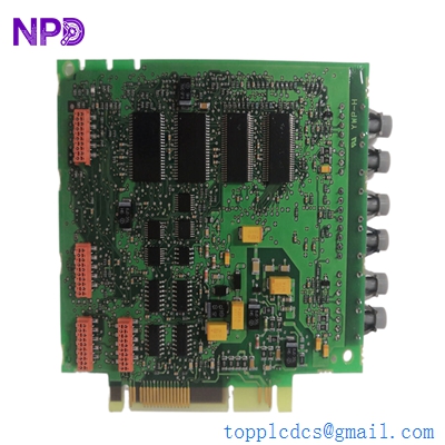

Description
- Model: ABB PU515A (Part No. 3BSE032401R1)
- Brand: ABB (Sweden)
- Series: Advant OCS / 800xA Communication
- Core Function: Remote Terminal Adapter (RTA) for high-speed control networking
- Condition: Brand New Surplus (Original New), Non-refurbished
- Type: Communication Interface Module
- Key Specs: Supports AF100 Bus RTA technology Redundancy compatible
- Processor: High-performance RTA (Remote Terminal Adapter) logic
- Communication Protocol: Advant Fieldbus 100 (AF100)
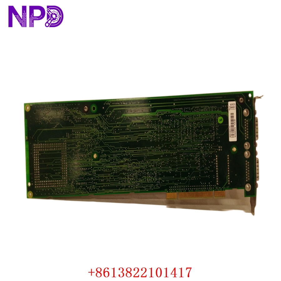
- Interface: PCI or proprietary backplane interface (depending on carrier)
- Memory: Integrated flash and RAM for buffer management
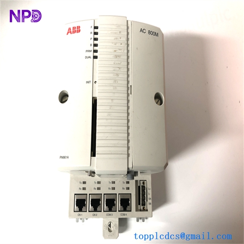
- Indicators: Front-panel LEDs for RUN, FAULT, and BUS STATUS
- Power Consumption: Typically 5 W at +5 V DC (via backplane)
- Redundancy: Support for dual-cable AF100 configurations
- Operating Temperature: 0 °C to +55 °C
- Compatibility: Used in AC 410, AC 450, and 800xA connectivity servers
- Firmware: Pre-loaded with standard ABB RTA software
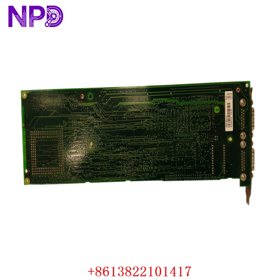
ABB PU515A 3BSE032401R1

ABB PU515A 3BSE032401R1
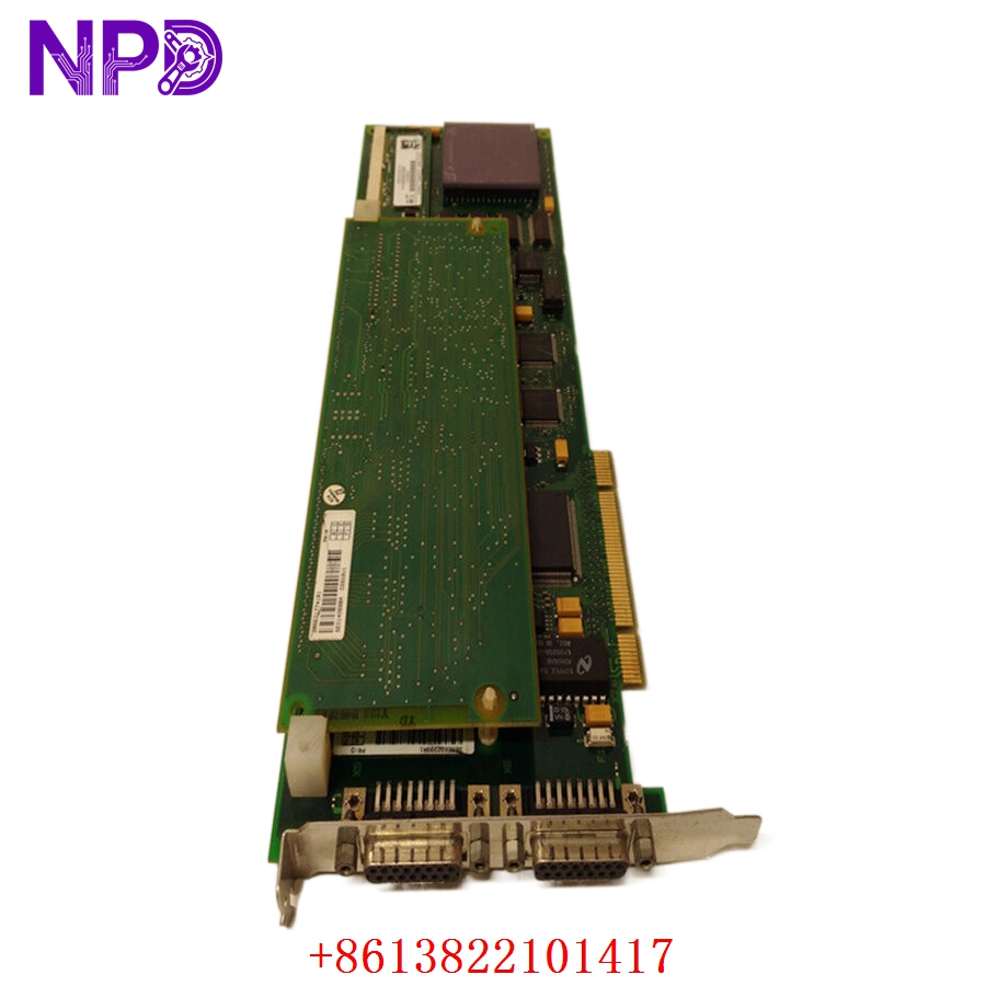
ABB PU515A 3BSE032401R1
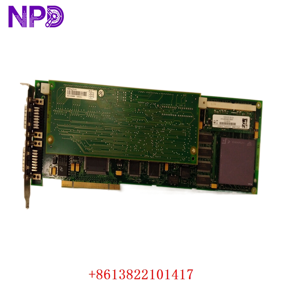
ABB PU515A 3BSE032401R1
Installation & Configuration Guide
Phase 1: Preparation (15 Minutes)
⚠️ Safety First:
- The PU515A is a critical communication bridge. Its failure or incorrect removal can drop an entire segment of the plant off the control network.
- Ensure you have a current “Bus Map” of your AF100 network.
- Check the version of your Connectivity Server or AC 400 controller software to ensure the 3BSE032401R1 revision is supported.
Tools & Protection:
- ESD wrist strap (Crucial—the RTA chips are extremely sensitive to static).
- Small Phillips screwdriver for faceplate screws.
- Fiber-optic or Coax cleaning kit (if using external modems).
Phase 2: Removal (10 Minutes)
- System State: In a redundant system, verify that the “Partner” RTA is healthy and has taken over the primary role.
- Disconnecting: Unplug the AF100 cables (or the interface to the modems). Mark them “A” and “B” to prevent crossing.
- Extraction: Loosen the captive screws on the PU515A faceplate. Use the injector/ejector handles to pull the module out of the slot.
- Slot Inspection: Check for dust or debris in the backplane connector.
Phase 3: Installation (20 Minutes)
- Address Check: If the board has hardware jumpers or DIP switches for the Station Address, set them exactly like the old unit.
- Seating: Slide the new PU515A into the carrier slot. Press the handles inward to seat the module.
- Securing: Tighten the faceplate screws to ensure a solid ground path.
- Cabling: Reconnect the AF100 interface. In my experience, ensuring the connectors are tightened just past “finger-tight” prevents vibration-related signal loss.
Phase 4: Power-On & Testing (30 Minutes)
- LED Check: Apply power.
- RUN (Green): Should flicker then stay solid.
- FAULT (Red): Should be OFF. If it stays on, there is a hardware ID conflict or internal failure.
- Network Sync: From the Engineering Station, check the AF100 status. The PU515A should appear as “Operational” or “Active.”
- Load Test: Monitor the “Error Counter” for the specific station. A healthy 3BSE032401R1 should show zero or near-zero CRC errors.
Customer Cases & Industry Applications
Case 1: Resolving Intermittent Bus Faults in a Power Plant
Situation: A coal-fired power plant in Asia experienced intermittent “Communication Lost” alarms between the AC 450 controller and the operator stations. Task: The troubleshooting team identified a degrading RTA unit that was dropping packets during peak network traffic. Action: We supplied a New Surplus PU515A. Result: The intermittent alarms disappeared immediately. The plant’s MTBF (Mean Time Between Failures) for the control network increased significantly, and they purchased an additional unit as a “hot spare.”
Case 2: Connectivity Server Upgrade
Situation: A refinery was upgrading their 800xA Connectivity Servers. They needed brand-new communication interfaces to match the reliability of the new server hardware. Task: They required five PU515A modules with matching firmware versions. Action: We provided five factory-sealed units from the same production batch. Result: The migration was seamless. By using New Surplus instead of used parts, the refinery ensured another 10+ years of life for their AF100 bus architecture.
Frequently Asked Questions (FAQ)
Q: Can I use PU515A to replace a PU515? A: The “A” version is the improved revision of the original PU515. In 99% of cases, it is a direct replacement. However, check your controller firmware version, as very old systems (pre-1998) may require a minor software patch to recognize the newer hardware ID.
Q: Is this module hot-swappable? A: Technically, the hardware supports it in many carriers, but the AF100 protocol does not like sudden “disappearances.” In my experience, it is always safer to put the controller or server in a “Service” mode before swapping the PU515A.
Q: Why is “New Surplus” better for a communication module? A: Communication modules like the 3BSE032401R1 use high-speed logic chips that generate significant heat. Used modules have been “baking” in cabinets for years, which degrades the timing oscillators. A New Surplus unit has a fresh oscillator, ensuring the timing on the AF100 bus is perfect.
Q: Does it come with the AF100 termination resistors? A: No, the termination is usually handled on the cable or the bus tap. The PU515A is the processing module only.
Q: How do I verify the firmware version? A: You can read the firmware version via the ABB tool “Bus Configuration” or by looking at the sticker on the EPROM chip on the side of the PCB. If you need a specific version, please let us know before we ship.