
Description
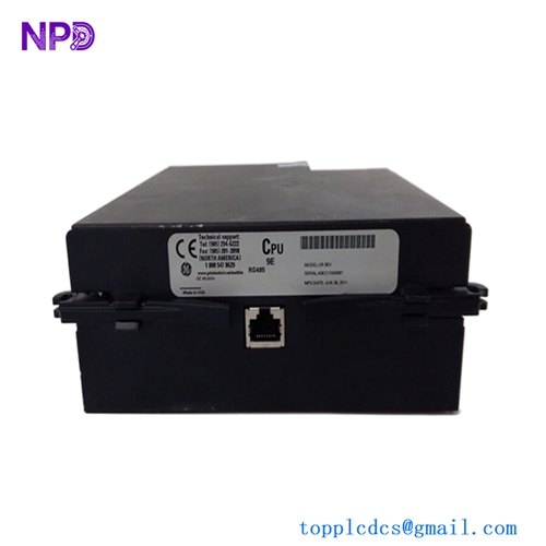
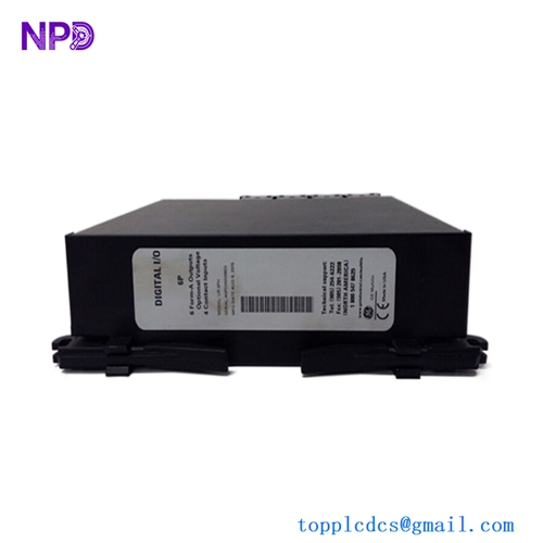
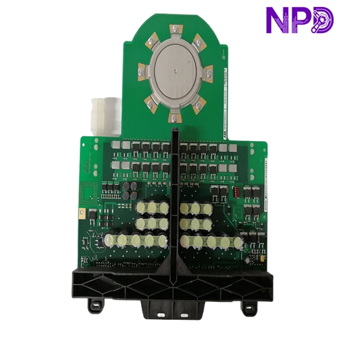
The ABB Bailey IMDS014 is a high-density Digital Output Module designed for use within the INFI 90 and Harmony distributed control systems. This module provides the interface between the control system’s digital logic and field devices, such as relays, solenoid valves, and indicator lamps. It is essential for executing discrete control commands in industrial environments like power generation and water treatment, where reliability and signal isolation are paramount.
Product Specifications
📍 Product Series: Bailey INFI 90 / Harmony
⚖️ Weight: 0.8 kg
📏 Dimensions: 340 mm x 250 mm x 30 mm
🌍 Country of Origin: USA
⚡ Operating Voltage: 24 V DC (Standard logic level)
🔄 Output Type: 16-channel discrete output (Open collector or relay configurable)
🛡️ Protection Class: IP20
🌡️ Operating Temperature: 0°C to +70°C
🏗️ Mounting Type: Harmony Rack / Module Bus slot
🔌 Interface: Edge connector for module bus communication
Technical Architecture
The IMDS014 module serves as a bridge, translating software-defined control signals into physical current loops. To ensure plant safety, these modules are typically optically isolated from the main backplane. This prevents electrical faults in the field from propagating back to the sensitive central processor.
Recommended Models in the Same Series
🔍 IMDS002: Low-density 8-channel digital output module.
🔍 IMDS014-R: Factory-refurbished certified unit.
🔍 IMDIS014: Digital Input module pairing for the IMDS014.
🔍 IMMFP01: Multi-Function Processor module (typically coordinates with IMDS series).
🔍 IMDSO14-B: Version with enhanced surge protection for outdoor installations.
🔍 NKTU01: Termination unit for field wiring of IMDS014 modules.
🔍 IMDSI12: 16-channel Digital Input module for high-density feedback.
🔍 INFI-90-Rack-Backplane: Spare backplane for modular expansion.
🔍 IMDS014-Connector: Replacement edge connector housing and pins.
🔍 ABB-Harmony-I/O-Extension: Cable assembly for remote mounting configurations.
Diagnostic Troubleshooting If you encounter a “Module Communication Fail” error in your control loop, check the Module Bus address switches on the front of the unit first. If the outputs are not engaging despite the software status being “ON,” inspect the local LED indicators; if they are illuminated but the field device is inactive, the fault is likely in the external field power supply or the output relay/transistor stage.